LIGHTMED TruScan Pro – Operator’s Manual Rev. No. 01 Page 84 of 109
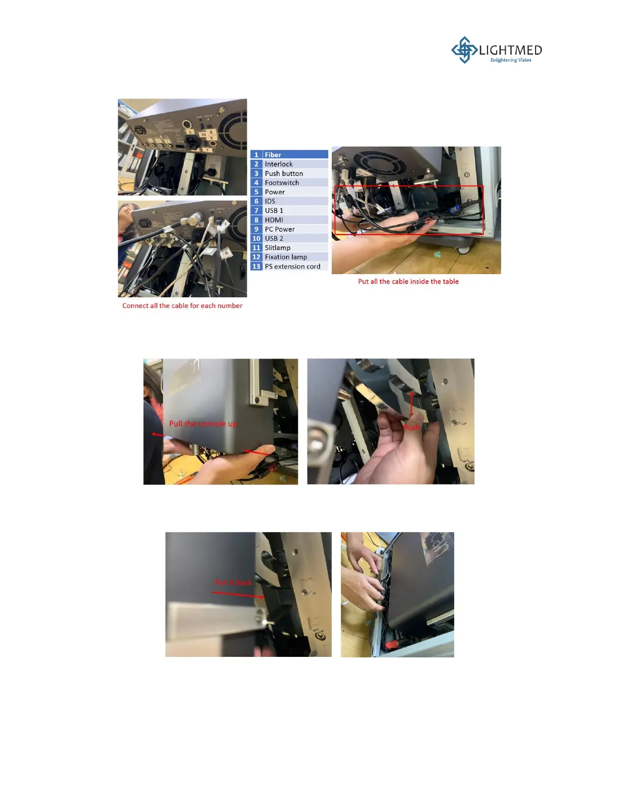
20. Connect all the cables according to their respective number labels and properly store the
cables inside the table (Figure 33).
Figure 33: Connecting the cables to the laser console.
21. To place the mounted console back into the hanger cavity, carefully push the console and the
hanger upwards to release the hanger from the stopper (Figure 34).
Figure 34: Releasing console hanger from the stopper.
22. With the hanger released from its stopper, the hanger can now be pushed back into the hanger
cavity, putting the laser console in place inside the console cover (Figure 35).
Figure 35: Pushing the console hanger back into the hanger cavity.
23. Locate the tab on the fiber assembly. This tab must be positioned accordingly into the
corresponding notch at the face of Port 1 on the laser console (Figure 36). If these tab and
notch do not match or properly secured, the sensor in Port 1 will not be able to recognize the