LIGHTMED TruScan Pro – Operator’s Manual Rev. No. 01 Page 85 of 109
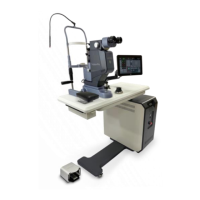
delivery system, thus a warning prompt will be displayed on the LCD screen. Once the tab
and notch are positioned correctly, screw (clockwise) the fiber assembly into the laser console.
Please be noticed that Port 1 is designed specifically for fiber assemblies, while Port 2 is
catered to the LIO assembly.
Figure 36: Inserting the fiber assembly into Port 1 of the laser console.
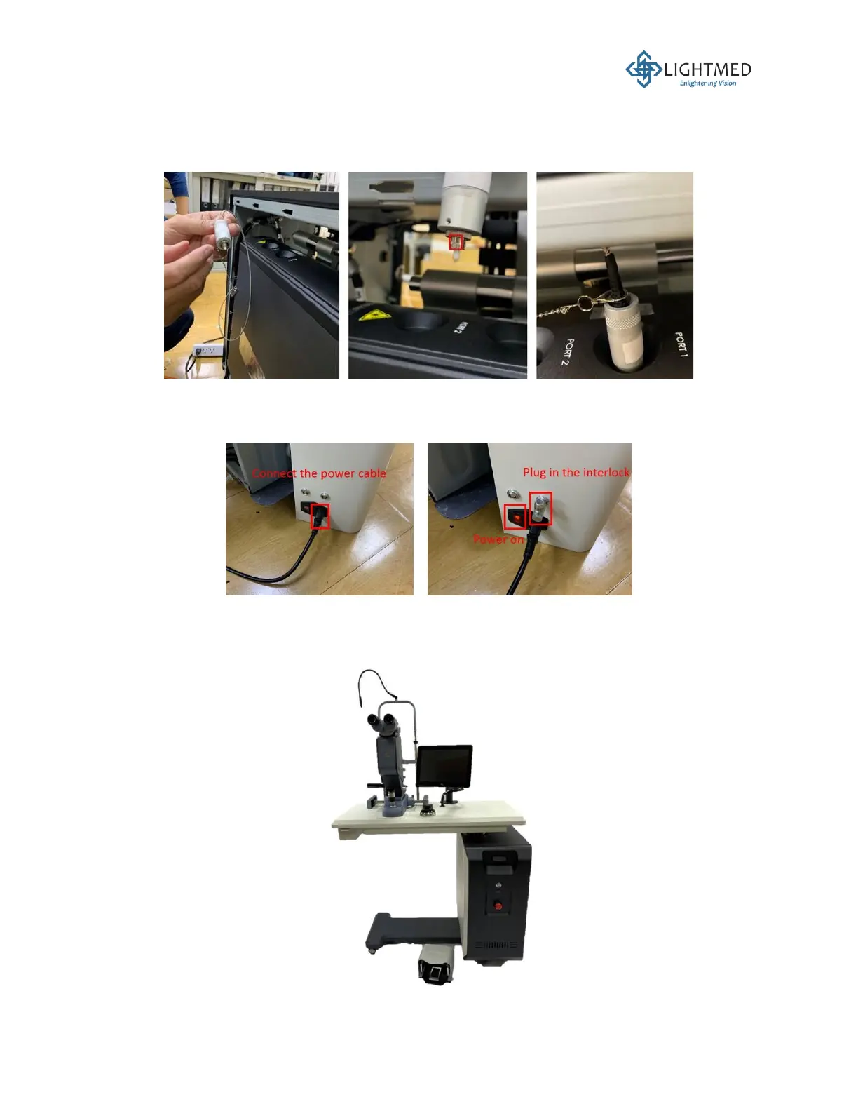
24. Connect the main power cable to the inlet on the right console holder cover (Figure 37). Plug
in the interlock key. Press the power switch to turn the table ON.
Figure 37: Turning the system ON.
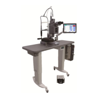
25. The installation for the ophthalmic table is completed (Figure 38). Complete the Installation
Report on page 91.
Figure 38: Final assembly of the TruScan Pro laser system.