6)
11)
14) 13)
10)
12)
4)
7)
5) 3) 2)
1)
8)
9)
-12-
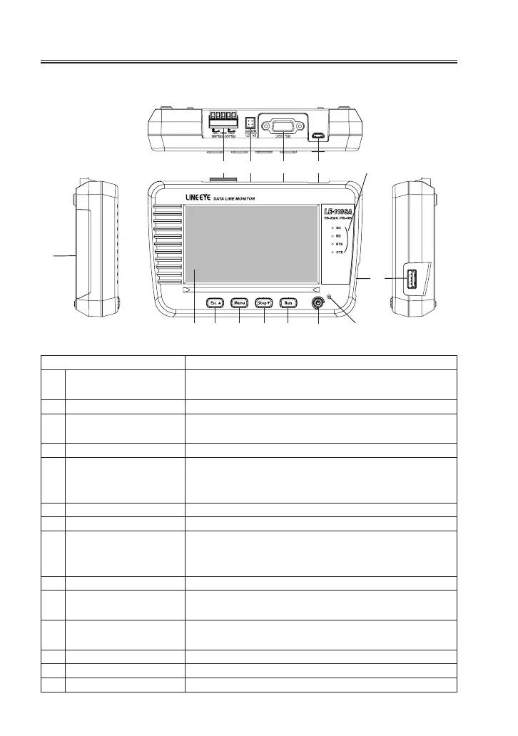
1.4 Explanation of Each Part
[
LE -110SA
]
Name Function
1) Power Switch
Turn on / o the power.
Press for a while to turn o the power.
2) [ Run ] key Start monitoring / simulating.
3) [ Stop ] key
Stop monitoring / simulating.
Scroll data (forward). Search data.
4) [ Menu ] key Display the top menu.
5) [ Esc ] key
Return to the previous display.
Scroll data (backward). Search data.
Stop displaying data while measuring.
6) 4.3 inch color LCD with touch panel.
7) Line State LED Light in red when signal is active.
8) Power LED
Light in green when turning on the power.
Light in red: battery full charged. Blink in red:
Still charging the battery.
9) Battery Cover Open when changing the batteries.
10) USB Device Port
Micro-USB connector.
Connect to the USB port of PC or USB battery charger.
11) USB Host Port
Standard A USB connector. Connect to the USB ash
drive.
12) RS-232CPort RS-232C measurement port.
13) External Trigger Port Input / output port for external trigger signals.
14) RS-422 / 485 Port RS-422 / RS-485 measurement port.
L C D
 Loading...