5.2 Start and Stop Monitoring
Setting and Connection
Select a measurement port, conditions for monitoring and communication
conditions.
Connect the line monitor and target devices.
→ 3.2 Measurement Port / Function
→ 3.3 Communication Speed
→ Chapter 4 Connect to the Target Devices
Set “Record control” such as time stamp and control line settings.
→ 3.6 Idle Time and Time Stamp
→ 3.7 Line State
Start Monitoring
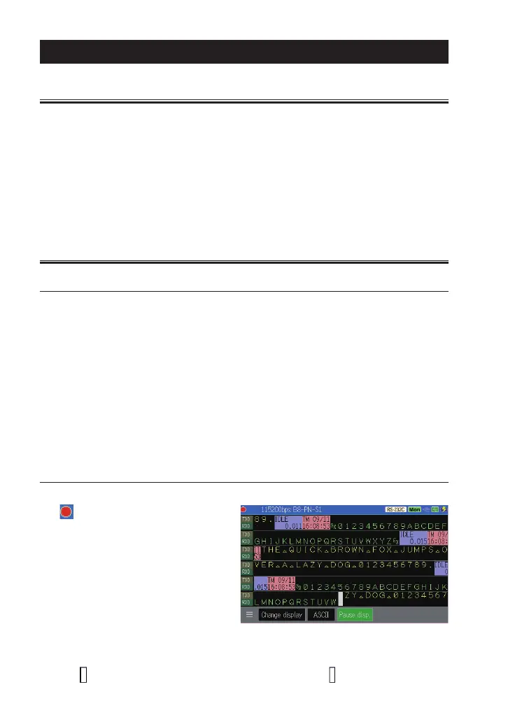
Press [Run] to start monitoring.
“ ” will be displayed in the
upper left. Measured data is
displayed at real time and record
data in the capture memory. Send
(TXD) data and receive (RXD)
data are displayed in two lines as
a pair.
If send and receive data are measured at the same time, they are displayed in the
same column.
“ ” indicates the recent data and the very left side of “ ” is the latest data.
-34-
Chapter 5 Monitor Function
5.1 Overview
Monitor function records communication data in the capture buer without
impacting on a communication channel. Communication data is displayed
with time stamp, idle time, control signals and state of external trigger at
real time. As a result, error time and time out conditions can be investigated.
Moreover, the trigger function, which detects specific communication
conditions, and filter function for specific address frame, which makes a
memory eectively used, are included.
 Loading...