-31-
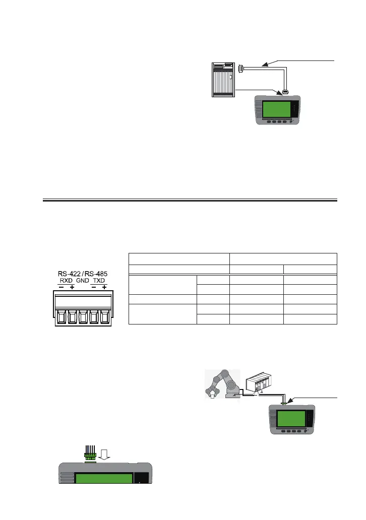
4.2 Connect to RS-422/RS-485(LE-110SA)
Set “Measurement port: RS-422/485” before measuring RS-422/485.
→ 3.2 Measurement Port / Function
<
RS-422/485 Port
>
Removable terminal block
(*1)
Signal input/output
(*2)
Signal name To monitor To simulate
Transmission data
TXD+ I O
TXD- I O
Receiving data GND - -
Receiving data
RXD+ I I
RXD- I I
*1
:
5 poles 3.81mm pitch. Appropriate wire: Single, twisted wire
“AWG28-16”.
*2
:
“I” indicates the input to the line monitor. “O” indicates the output
from the line monitor.
RS-422/485 port of line monitor has a
removable terminal block. Remove the
terminal block from the line monitor
before wiring the twisted pair cables.
■
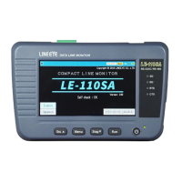
To simulate data
Select “Simulation” mode and press
[Run] . RS-232C port of linemonitor
will be DTE specication (equivalent
to COM port). Check the DTE/DCE
specification of targetdevice and
connect to the linemonitor, using
straight or cross cable.
RS-232C CABLE
RS-232C Port
Dsub9
Target Device (DCE specication) ---- Straight cable ---- line monitor
Target Device (DTE specication) ---- Cross cable ---- line monitor
RS-422/
RS-485Port
 Loading...