-32-
■
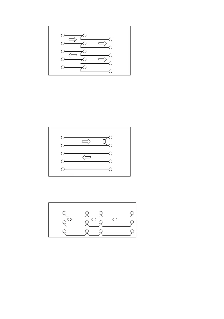
Monitor RS-422 between Device A and Device B
We recommend connecting “TXD+” to “TXD-” and “RXD+” to “RXD-”
using twisted pair cables.
If your target devices have “TXDA” and “TXDB”, conrm which one is the
positive and the negative.
Connect the signal ground of target device and GND of line monitor certainly.
■
Simulate data from line monitor to RS-422 Device.
Connect the terminal control of 100Ω-120Ω in between RXD+ and RXD-.
■
Monitor or Simulate RS-485
Line monitor is connected as one of RS-485 nodes when measuring half-
duplex RS-485.
If the line monitor is the terminal device, connect the terminal control (100Ω-
120Ω) in between TXD+ and TXD-.
The send and receive data of RS-485 is displayed in the TSD line of line
monitor.
Device A Device B LE-110SA
TXD+
TXD-
TXD+
TXD-
TXD+
TXD-
RXD+
RXD-
RXD+
RXD-
RXD+
RXD-
SG SG
GND
Device LE-110SA
TXD+
TXD-
TXD+
TXD-
RXD+
RXD-
RXD+
RXD-
SG
GND
Terminal
control
Device A Device B LE-110SA
TX/R
X+
TX/RX-
SG
SG SG
Device C
GND
TX/RX+
TX/RX-
TX/RX+
TX/RX-
TXD+
TXD-
 Loading...