-33-
4.3 Connect to TTL interface(LE-120SA)
Select an appropriate voltage level of TTL in the line monitor setting before
measuring TTL (UART) signals.
→ 3.2 Measurement Port / Function
<
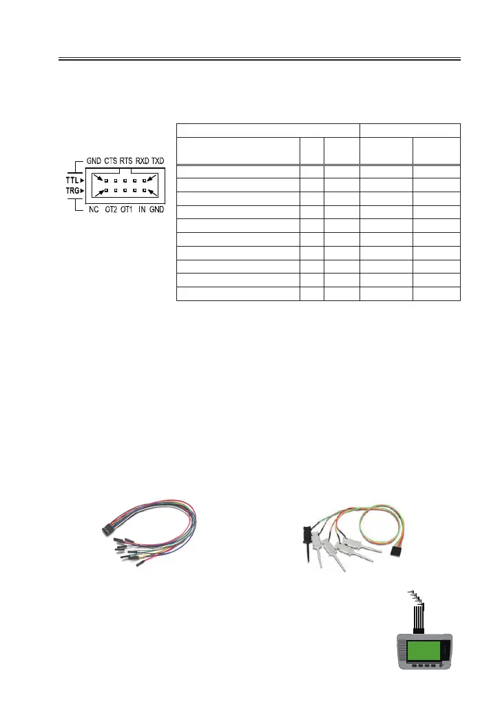
TTLPort
>
* 1
:
2 lines.2.54mm pitch. Equivalent to “HIF3FC-10PA-2.54DS(71)”
of HIROSE Electric. CO., LTD.
* 2
:
Lead colors of attached cable (LE10ES1) and optional cable (LE-
5LS).
Connect TTL (UART) signals of target device to the TTL port of line
monitor.
Use 10pins external input / output cable (LE-10ES1) if the signals of target
device are long enough to connect.
Use optional 5lines probe cable (LE-5LS) to pinch the signal of target device.
10pins external input/ output cable
5lines probe cable
MIL box type 10pin cable
*1
Cable color
*2
Signal name Pin Input/
output
LE-10ES1 LE-5LS
TXD TTL monitor input 1 I Brown Brown
RXD TTL monitor input 3 I Orange Red
RTS TTL monitor input 5 I Green Orange
CTS TTL monitor input 7 I Purple Yel low
Signal ground 9 - White Green
Signal ground 2 - Red
IN trigger input 4 I Yel low
OT1 trigger output1 6 O blue
OT2 trigger output2 8 O Gray
NC Not Connected 10 - Black
1
2
9
10
length
300mm
accessory
:
LE-10ES1
length
360mm
Option
:
LE-5LS
 Loading...