68 CHAPTER 6: OPERATION
QUICK LOAD SERVO 80 S2
Display
The liquid crystal display provides the operator with all the necessary data, both for handling the bar feed
system and for maintenance.
· The upper portion of the display has eleven lines and is reserved for the reading of text.
Error messages are usually displayed with their diagnostics.
· The lower portion of the display is reserved for the display of icons. The icons indicate to the
operator which functions are attributed to keys F1 through F4.
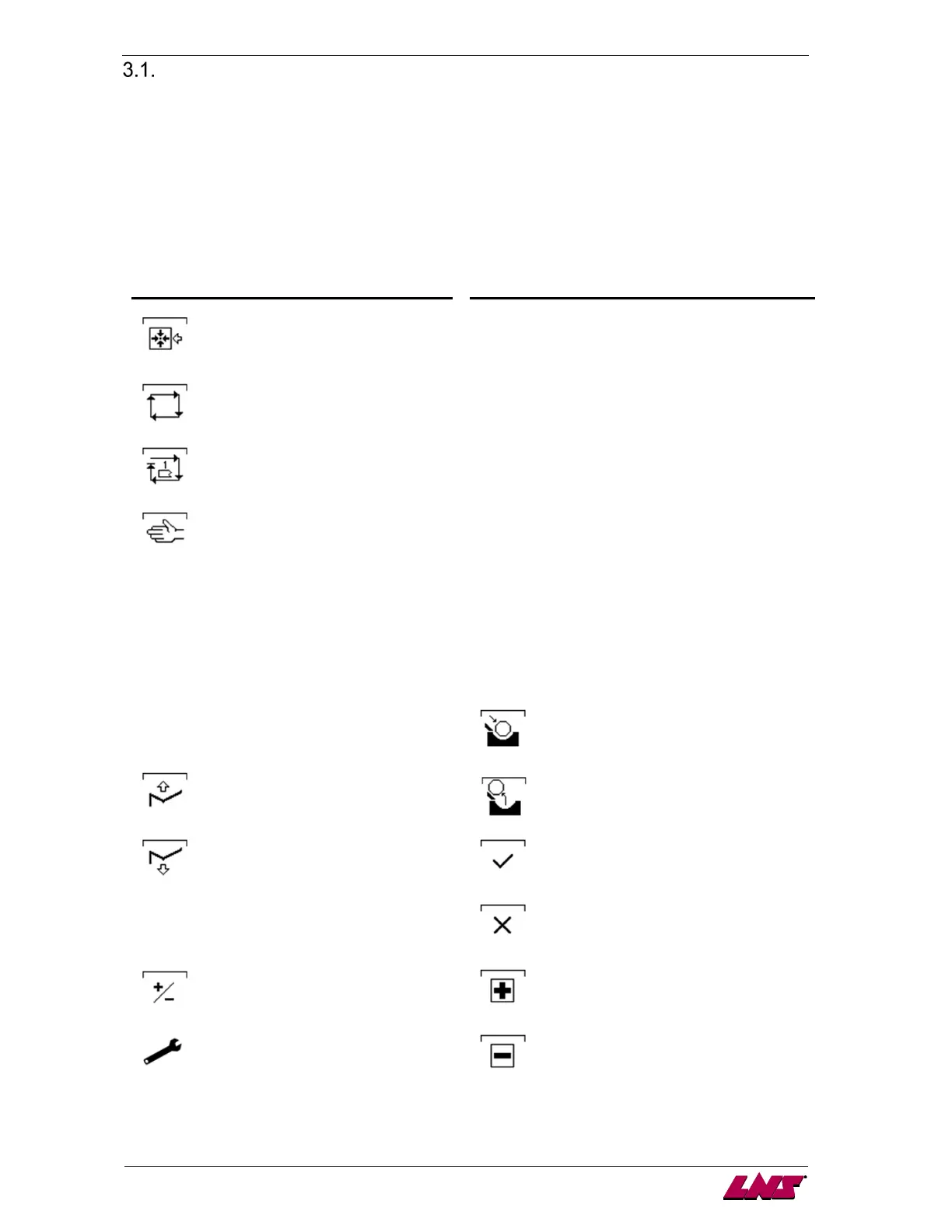
The icons available are the following:
Icon Signification Icon Signification
Referencing position
ENTER Confirm
Switch to automatic mode
START Start sequence
Stop after machining one bar stock
SET Set up
Switch to manual mode
ESC Escape
FWD >>
Pusher forward (picture may be
reversed)
PAGE
UP
Return to previous menu
<< REW
Pusher reverse (picture may be
reversed)
PAGE
DOWN
Jump to next menu
TOP
CUT
Automatic Top-Cut positioning in manual
mode
Load a bar in the guiding channel.
Raise the loading table
Confirm that the bar has been extracted
manually from the guide channel
Lower the loading table
Validate
TEACH
IN
Teach data
Cancel
Offset correction
Increment data in offset correction mode
Setup menu
Decrement data in offset correction mode
 Loading...