1) After the machine is powered on, inspect whether instrument indications are normal;
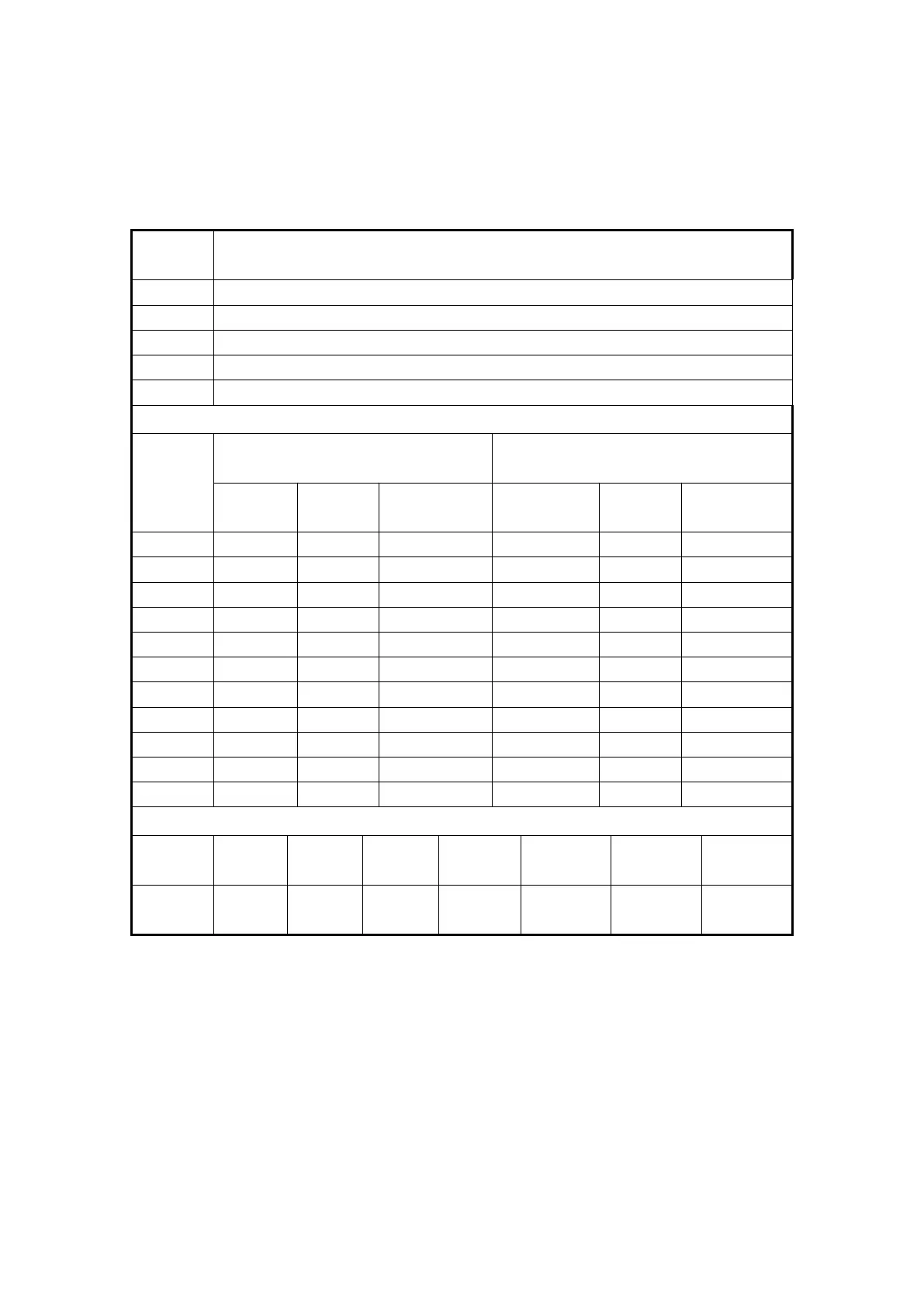
2) In case of any failure, first inspect whether the sensors are damaged or not; in case
of no damage, inspect the corresponding temperatures in the following table to confirm
whether the resistances meet the requirements in the table below.
3) If the sensor is fault-free, then inspect the cable from each sensor to the front of the
instrument, to inspect whether
it
is normal without damage or not.
4) If there is no damage, then loose, short circuit and, connect a small resistor in series,
then the indicator will display the max. value, the indicating hand does not point to a
mark, if
it
cannot normally indicate, and then replace the meter.
5.9.3
5.9.3
5.9.3
5.9.3 SOLDERING
SOLDERING
SOLDERING
SOLDERING
Comparison of the temperature sensor parameters
Pressure sensor parameters comparison
1.0MPa hydraulic and pneumatic
sensors
2.5MPa air pressure sensor
General Parameters of Fuel Sensor