Lucent Technologies -48V CPS4000/CPS4000 PLUS Cabinet Power System
5 - 16 Installation and Testing Issue 13 December 2000
Plug-In Modules, continued
Procedure
Plug-in Modules
Step Action
1
Verify that the proper modules have been ordered and
received.
2
Disconnect the power to the shelf by turning the ac service
circuit breakers Off.
3
Place On/Standby switch on each rectifier or converter to the
Standby position.
Caution
To avoid arcing on the contacts of the interface connector,
the On/Standby switch on each rectifier or converter must
be in the Standby position before installing the module.
4
Install each rectifier and/or converter and/or ringer by placing
it on the CPS shelf, beginning with the left-most position slot
#1, and carefully sliding it toward the backplane until its
mounting screw prevents any further backward motion. Do
not seat the rectifiers.
5
If provided, remove the BSP2 or BSP2C module and verify
the low-voltage disconnect/reconnect threshold setting.
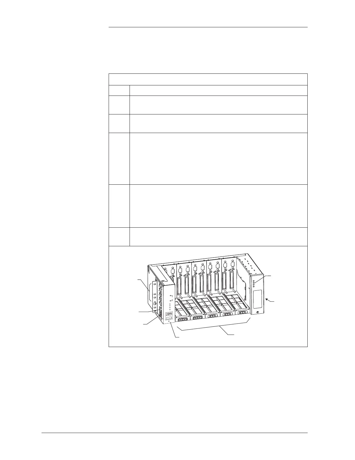
Control Unit
Output Section
LVD/Thermal
Management
Circuit Pack
Power Unit Slots for Rectifiers,
Converters, and Distribution Modules
Slot 1
Slot 2
Slot 3
Slot 4
Slot 5
Commercial
AC Input Power
J6: Office Alarm
Connector
J7: Intershelf
Signal Connector
Normal
V
PMN
PMJ
V Adj
+
-