Lucent Technologies -48V CPS4000/CPS4000 PLUS Cabinet Power System
Issue 13 December 2000 Installation and Testing 5 - 7
Installing Shelves and Batteries, continued
Installing Batteries
Installing Batteries
Step Action
1
Verify that the proper batteries have been ordered and
received.
2
• To install Lucent Technologies 12IR125 or VR-type
batteries, refer to the appropriate product manuals. Follow
all safety precautions when installing batteries.
• To install a J85504D-1 IR 30/40 Battery Module, ensure
that adequate space is available for mounting the module.
Each module requires a minimum of nine inches of
vertical height. Modules to house IR30 batteries require
13 inches of depth; modules to house IR40 batteries
require 20 inches of depth. The battery module(s) should
be mounted as close to the -48V CPS shelf as practical,
preferably immediately below the shelf. The 1-inch
vertical space required to cool -48V CPS power shelves is
inherent in battery modules. See Figure 5-3.
Warning
For safety reasons, the batteries must be disconnected
while installing and testing the equipment.
While installing batteries, follow all safety precautions
outlined in the appropriate battery product manuals.
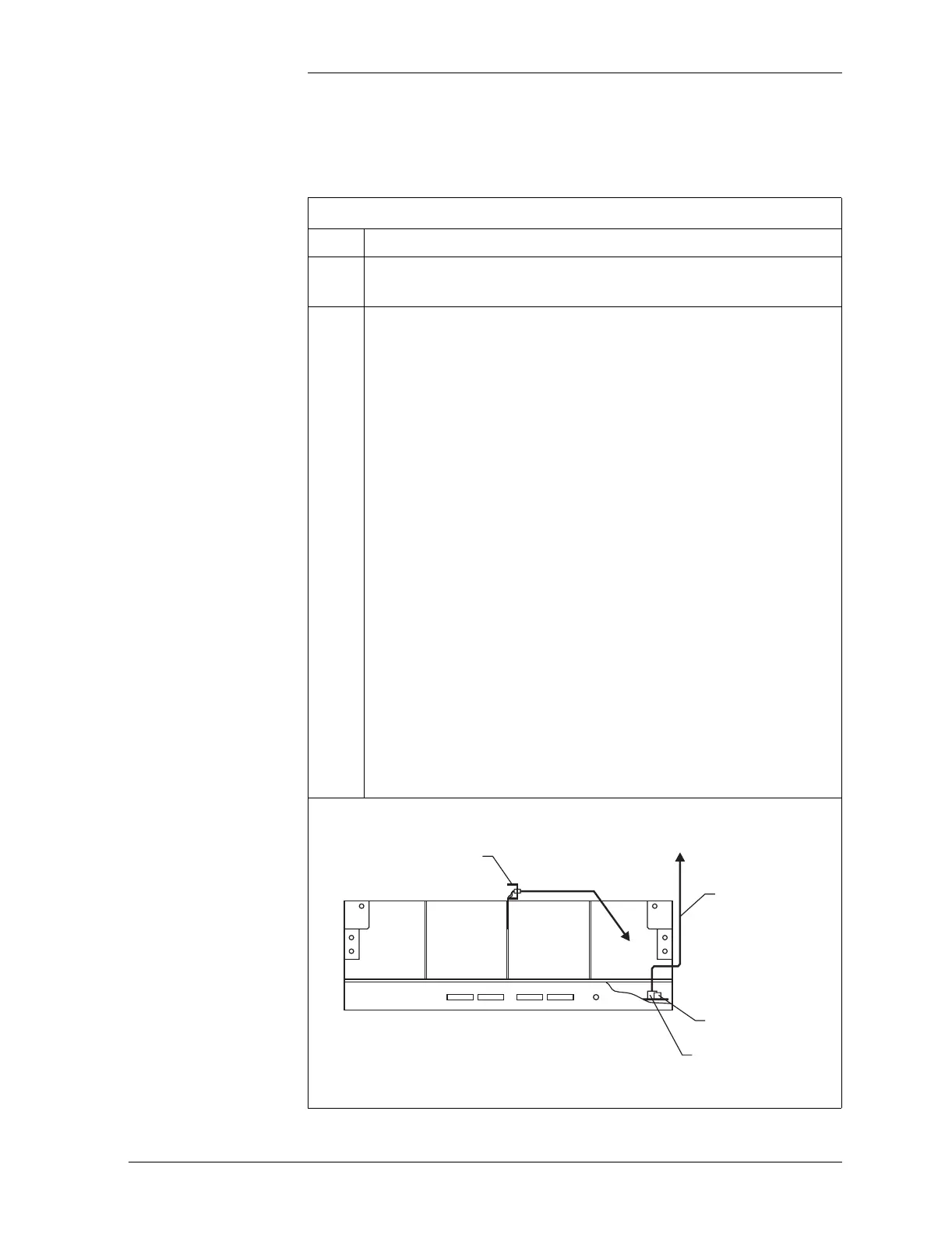
Figure 5-3: J85504D-1 Battery Module
Battery Voltage
Alarm
String A String B
P413 4-Pin
Connector
847157674
Cable Assembly
P409 6-Pin
Connector
J85504D-1 Battery Module
Front View
To P413
Thermistor Assembly
Temperature
Wire Set
To J10, J11, J12, or J13
on CPS Shelf