Lucent Technologies -48V CPS4000/CPS4000 PLUS Cabinet Power System
Issue 13 December 2000 Product Description 2 - 1
2 Product Description
Overview
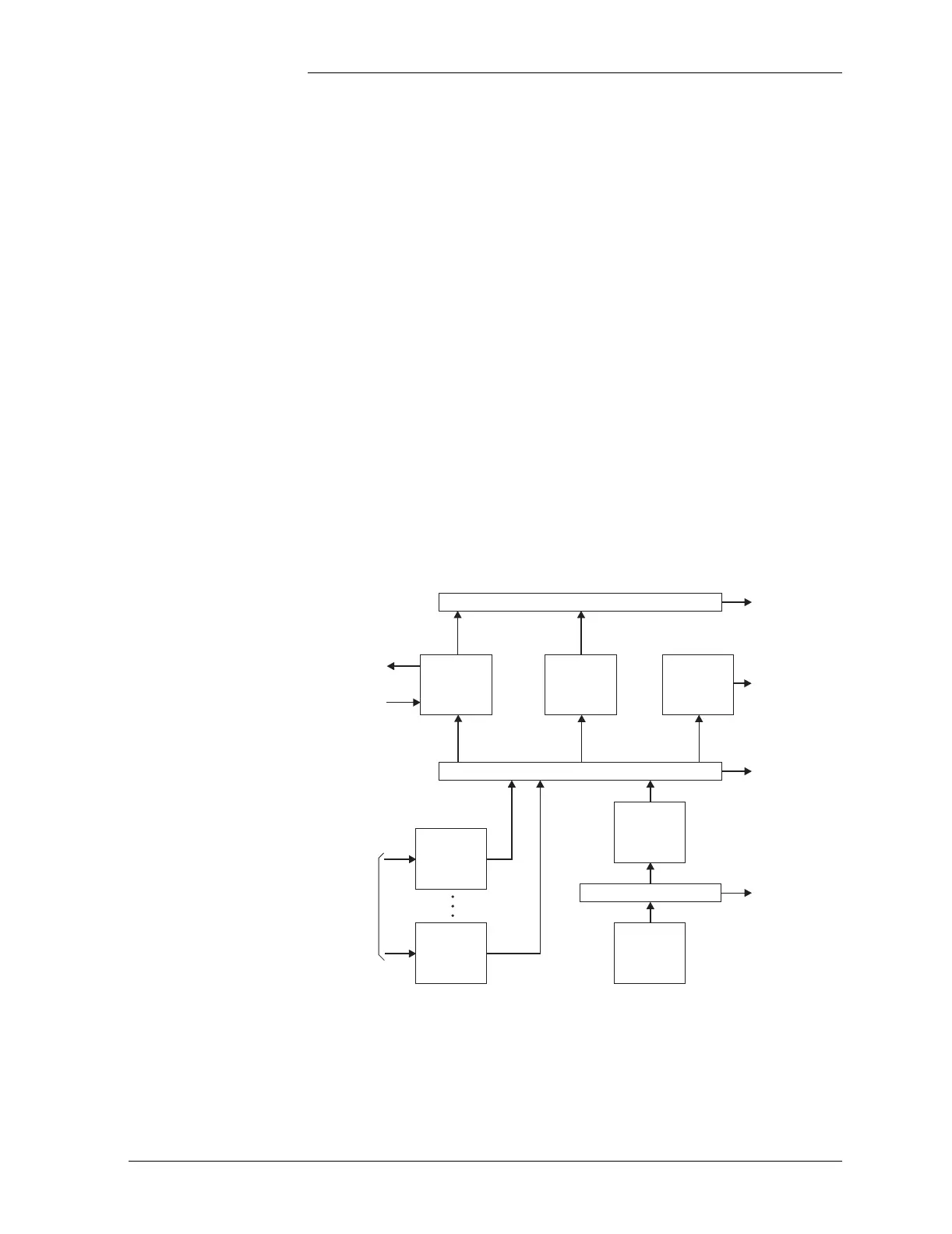
Block Diagrams Figure 2-1 is a basic block diagram of the -48V Cabinet Power System
(CPS) configured as an initial shelf or with Low-voltage Disconnect
(LVD).
Shelf assemblies house and interconnect power modules, a control unit,
and a distribution module.
Figure 2-1: Block Diagram of -48V CPS With LVD Contactor
Secondary Power Bus
Secondary
Output
Connector J14
Primary Power Bus
Primary Power Bus
Protected
Output
Primary
Output
Bus J3
Primary
Output
Bus J2
Rectifier
AC
Input
Rectifier
Low
Voltage
Disconnect
Battery
String(s)
Control
Unit
Office
Alarms
Battery
Temperature
Converters
Distribution
Module