Lucent Technologies -48V CPS4000/CPS4000 PLUS Cabinet Power System
Issue 13 December 2000 Installation and Testing 5 - 19
DC Distribution Wiring, continued
Kits Kits providing the cables and hardware needed for this procedure are
listed in Section 3, Engineering and Ordering.
Procedure Note: When running dc output cables, pair the positive and negative
conductors over as much of their length as possible to minimize loop
areas for EMI considerations.
DC Distribution Wiring
Step Action
1
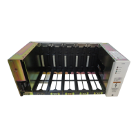
Remove the cover on the output distribution module (on the
far right of the shelf) using the 3/16" Allen wrench provided.
2
Determine the appropriate wire size for the load and return
leads.
3
Dress the wire from the load to the output port on the right of
the shelf.
4
Terminate the wire with the proper connector using the
proper crimping tool.
5
Apply heat-shrink tubing over the exposed barrel of the lug.
6
Secure the terminated wire to the correct output position on
the CPS shelf, and torque the lug fasteners to 65 in-lbs.
7
Strain relieve these wires as appropriate to remove undue
stress on the connectors.
Warning
CPS shelves equipped with ES680 converters or ES620/ES621/
ES621A/ES621B/ES622C ringers have hazardous voltages on the
secondary bus output connector (J14). Ring signal cadencing and
tripping device must be provided by end-use product. In all
applications, exposed primary output bus bars have hazardous
energy levels.