Lucent Technologies -48V CPS4000/CPS4000 PLUS Cabinet Power System
Issue 13 December 2000 Installation and Testing 5 - 37
Initial Start-up and Test, continued
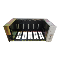
LVD Test
J85504D-1 Battery
Module Alarm
Connect batteries to the plant before administering this test.
LVD Test
Step Action
1
To simulate a failed low-voltage disconnect contactor:
a. Remove modules in slots 4 and 5 (right-most slots) in the
CPS initial shelf.
b. Remove shelf liner in slot 5.
c. Remove black plastic cover on the LVD compartment.
d. Remove one Quick-Connect
®
connector from the LVD
contactor coil.
e. Verify:
– LVD Open LED lights on the output module
– PMJ LED lights on the control unit
f. Clear these alarms by reconnecting the Quick-Connect
®
connector.
g. Replace the shelf liner in slot 5 and the modules in slots 4
and 5.
2
Reconnect the thermal probe cables (P10/P13) on the output
distribution board (J10-J13).
J85504D-1 Battery Module Alarm
Step Action
1
Simulate a battery module alarm (if equipped) by inserting a
blown GMT-type fuse in H101 or H102 on the J85504D-1
Battery Module circuit board.
2
Verify that the PMJ LED lights on the control unit. Clear this
alarm by replacing the fuse.