363-206-295
Power
4-2 Issue 1 December 1997
Power Description 4
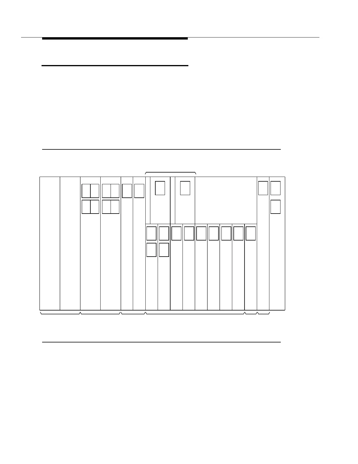
Two independent −48 volt office power feeders (A and B) enter the shelf through
backplane connectors and are fused and filtered at the user panel, then
distributed to the circuit packs. Power conversion is performed through modular
power converters located on the circuit packs. In each circuit pack, the two
feeders are diode ORed, fused, filtered, and regulated by the board-mounted
power modules. This provides the required redundancy in case of the loss of one
feeder or one fuse. Figure 4-1 shows which circuit packs have converters
mounted on the printed wiring boards. Power modules are located on the OLIU,
3DS3, 3STS1E, TSI, TG, SYSCTL, and OHCTL circuit packs.
Figure 4-1. DDM-2000 OC-12 Multiplexer Power Architecture
T T
-2.3V
TSI
S
I
1
S
I
to to
+15V
U
O
L
I
2(P)
1
-2.3V
to
+15V
to
U
O
L
I
1 2(P)
Main A Main B
2
A
P
P
B
L
K
1
7
7
C
A
P
P
B
L
K
1
7
7
C
-48V
+5V
-48V
to
+5V
-48V
to
+5V
to
TG TG
-48V
to
+5V
-48V
to
+5V
-48V
to
+5V
-48V
to
+5V
-48V
to
+5V
-48V
to
+5V
-5.2V
-48V
to
+5V
to
-48V
to
+5V
-48V
-48V
-48V
to
-5.2V
-48V
-5.2V
12
Timing
111
3333
3
D
S
3
D
S
3
D
S
3
D
S
1
-48V
to
+5V
-48V
to
+5V
to
-48V
UU
O
L
I
O
L
I
3
D
S
3
3
D
S
3
2(P) 2(P)
2(P)
2(P)
-5.2V
-48V
+5V
-48V
to
-48V -48V
to
Function Units
-48V
to
+5V
S
Y
S
C
T
L
-48V
to
+5V
O
H
C
T
L
-48V
U
S
E
R
P
A
N
E
L
A
Fuse
-48V
Fuse
B
SYSCTL
AUXCTL