363-206-295
Circuit Pack Descriptions
7-40 Issue 1 December 1997
BBG12 3STS1E Circuit Pack Description 7
Purpose of Circuit 7
The BBG12 3STS1E circuit pack provides bidirectional transport of up to three
EC-1 signals through the DDM-2000 OC-12 Multiplexer.
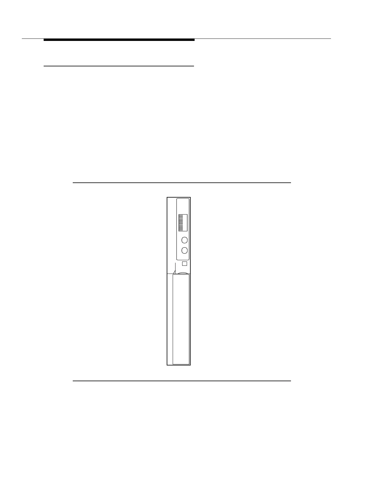
BBG12 3STS1E Faceplate Indicators 7
The BBG12 3STS1E circuit pack faceplate indicators are shown in Figure 7-16.
The red FAULT LED is lit by the SYSCTL on detection of the BBG12 3STS1E
circuit pack failure or by the loss of the circuit pack +5 V DC. In the event of an
incoming signal failure, this LED will flash on and off. The green ACTIVE LED
lights when the circuit pack is active (carrying service).
Figure 7-16. BBG12 3STS1E Circuit Pack
BBG12
E
Lucent
S1:1
T
ATIVC
FAU L
x
x
x
x
x
3STS1E