EasyManuals Logo

Lucent Technologies DDM-2000 OC-12 User Manual

Lucent Technologies DDM-2000 OC-12
1676 pages
To Next Page IconTo Next Page
To Previous Page IconTo Previous Page
Page #211 background imageLoading...
Page #211 background image
363-206-295
Circuit Pack Descriptions
7-10 Issue 1 December 1997
BBG8/BBG8B SYSCTL Hardware Setting 7
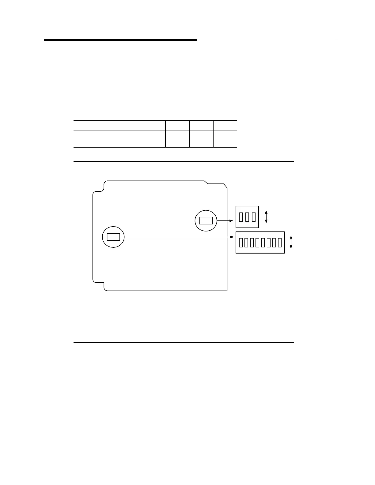
The BBG8/BBG8B has two hardware switches, Switch 1 (S1) for Product
Identification (see Figure 7-4) and Switch 2 (S2) for TBOS Termination used with
Release 5.x and earlier releases. Settings for S2 are not applicable for Release
7.0 and later releases.
Notes:
1. The switch is set by moving the slide toward the desired position.
2. The FAULT LED will also light if the companion OHCTL is not inserted.
Figure 7-4. BBG8/BBG8B SYSCTL Option Switches
Switch 1 (S1) Settings
VALUE S1-1 S1-2 S1-3
DDM-2000/
SLC
-2000/
DDM-2000 FiberReach
OFF OFF OFF
S1
12
ON
OFF
ON
S1
Edge
Connector
Component Side
S2
12345678
ON
OFF
ON
S2
3

Table of Contents

Other manuals for Lucent Technologies DDM-2000 OC-12

Questions and Answers:

Question and Answer IconNeed help?

Do you have a question about the Lucent Technologies DDM-2000 OC-12 and is the answer not in the manual?

Lucent Technologies DDM-2000 OC-12 Specifications

General IconGeneral
BrandLucent Technologies
ModelDDM-2000 OC-12
CategoryMultiplexer
LanguageEnglish

Related product manuals