363-206-295
Technical Specifications
10-36 Issue 1 December 1997
Power Dissipation 10
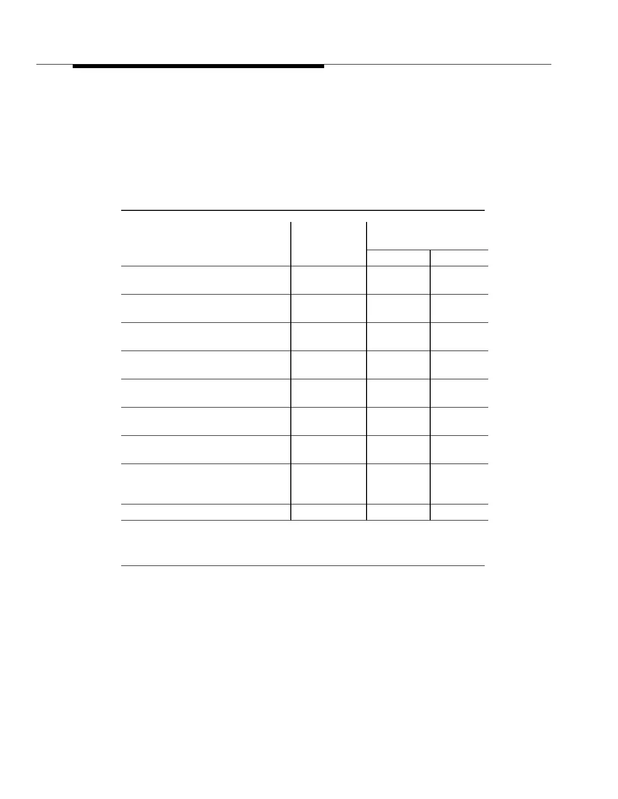
The power dissipation figures in Table 10-20 represent fully loaded shelves.
■ DDM-2000 OC-12 shelf accommodates two −48 V power feeders ("A" and
"B" office power feeders).
■ Table 10-20 lists the List 1 and List 2 power drain.
Table 10-20. Power Dissipation and Current Drains
Configuration
Power
Dissipation
(Watts)
DC Current Drains
(Amps)
L1 (−48V) L2 (−40V)
Pt-Pt DS3 Terminal
∗
(12 DS3)
177 3.7 4.4
21G/21G-U Optical Hub
∗
(4 OC-3)
201 4.2 5.0
21D/21D-U Optical Hub
∗
(4 OC-3)
193 4.0 4.8
OC-12 Regenerator
(4 REGENR circuit packs)
60 1.3 1.5
Pt-Pt EC-1 Terminal
∗
(12 EC-1)
177 3.7 4.4
Ring Shelf
∗
(12 EC-1)
187 3.9 4.7
Ring Shelf
∗
(12 DS3)
187 3.9 4.7
Ring Shelf
∗
E/W 21G/21G-U OLIU
(4 OC-3)
211 4.4 5.3
DDM-2000 Fan Shelf 53 1.1 1.3
* These configurations require the DDM-2000 Fan Shelf. Fan power
dissipation is listed separately.