363-206-295
Applications
Issue 1 December 1997 2-17
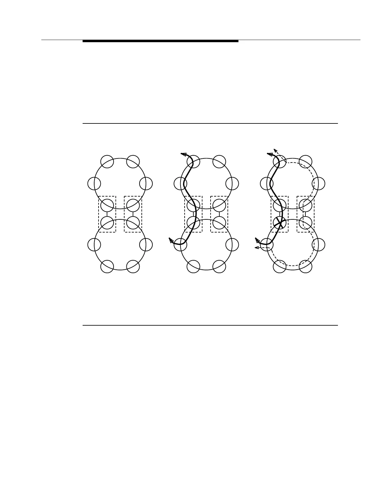
As Figure 2-10 shows, DRI allows a circuit (for instance, between nodes A and Z)
with one termination in the upper ring and the other termination in the lower ring to
survive a failure of the shared node that is currently carrying service for the circuit.
The failure is depicted by an "X" in the figure. The two shared nodes are in CO B
and CO C. Both nodes have the signal available to them at all times. When a
failure occurs, the two terminating nodes and the two shared nodes switch so that
traffic is carried through CO C and around the node failure.
Figure 2-10. Dual Ring Interworking Concepts
DUAL RING INTERWORKING
A
Z
A
Z
1. DRI Configuration:
Two Rings Interconnected
by Two Nodes
2. Circuit Originating
and Terminating in
Node A and Node Z
CO
B
CO
C
CO
B
CO
B
CO
C
CO
C
3. LOS Failure (Depicted by X)
at Node in CO B Triggers a
DRI Switch, That Automatically
Selects Traffic from Node in CO C.