EasyManuals Logo

Lucent Technologies DDM-2000 OC-12 User Manual

Lucent Technologies DDM-2000 OC-12
1676 pages
To Next Page IconTo Next Page
To Previous Page IconTo Previous Page
Page #218 background imageLoading...
Page #218 background image
363-206-295
Circuit Pack Descriptions
Issue 1 December 1997 7-17
TG Faceplate Indicators 7
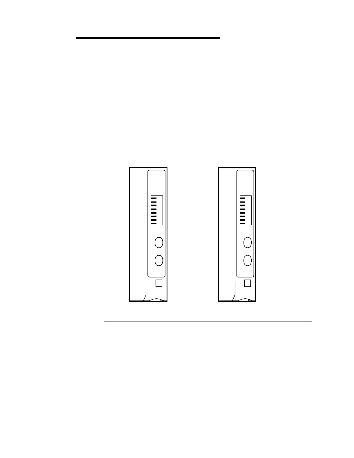
The TG circuit pack faceplate indicators are shown in Figure 7-7.
The red FAULT LED lights on detection of circuit pack hardware failure or
improper switch settings.
The red FAULT LED flashes in the event of an incoming DS1 timing reference
failure.
The green ACTIVE LED lights when the circuit pack is providing timing to the rest
of the shelf.
Figure 7-7. BBF2B TGS and BBF4 TG3 Circuit Pack
ATIVCE
Lucent
TGS
S1:1
FAU LT
x
x
x
x
x
BBF2B
ATIVCE
Lucent
TG3
S1:1
FAU LT
x
x
x
x
x
BBF4

Table of Contents

Other manuals for Lucent Technologies DDM-2000 OC-12

Questions and Answers:

Question and Answer IconNeed help?

Do you have a question about the Lucent Technologies DDM-2000 OC-12 and is the answer not in the manual?

Lucent Technologies DDM-2000 OC-12 Specifications

General IconGeneral
BrandLucent Technologies
ModelDDM-2000 OC-12
CategoryMultiplexer
LanguageEnglish

Related product manuals