363-206-295
Circuit Pack Descriptions
Issue 1 December 1997 7-25
Transmission 7
The transmission circuit packs are the BBG11 3DS3, BBG11B 3DS3, BBG12
3STS1E, BCP3 TSI FLEX, 21D/21D-U OLIU, 21G/21G-U/21G2-U OLIU, 23G/
23G-U OLIU, and the 23H/23H-U OLIU.
BBG11 3DS3 Circuit Pack Description 7
Purpose of Circuit 7
The BBG11 3DS3 circuit pack provides a low-speed interface between
asynchronous DS3 rate signals and SONET standard STS-1 signals.
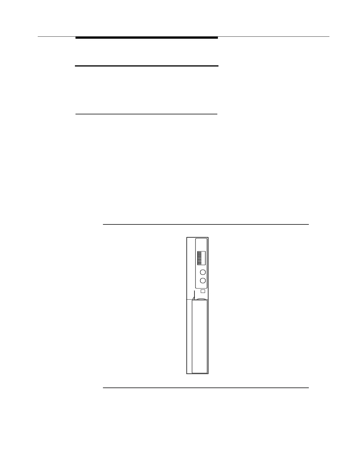
BBG11 3DS3 Faceplate Indicators 7
The BBG11 3DS3 circuit pack faceplate indicators are shown in Figure 7-10. The
red FAULT LED is lit by the SYSCTL on detection of the BBG11 3DS3 circuit pack
failure or by the loss of the circuit pack +5 V DC. In the event of an incoming signal
failure, this LED will flash on and off. The green ACTIVE LED lights when the
circuit pack is active (carrying service).
Figure 7-10. BBG11 3DS3 Circuit Pack
x
x
BBG11
x
x
x
LUAF
CVITA
3DS3
T
S1:1
Lucent
E