363-206-295
Circuit Pack Descriptions
Issue 1 December 1997 7-5
BBG8/BBG8B SYSCTL Circuit Pack Description 7
Purpose of Circuit 7
The BBG8/BBG8B SYSCTL circuit pack is the main system controller in the
system. Together with its companion OHCTL, it has control over all shelf functions
and provides all user interfaces into the system. The BBG8/BBG8B SYSCTL must
be used with the BCP4 OHCTL.
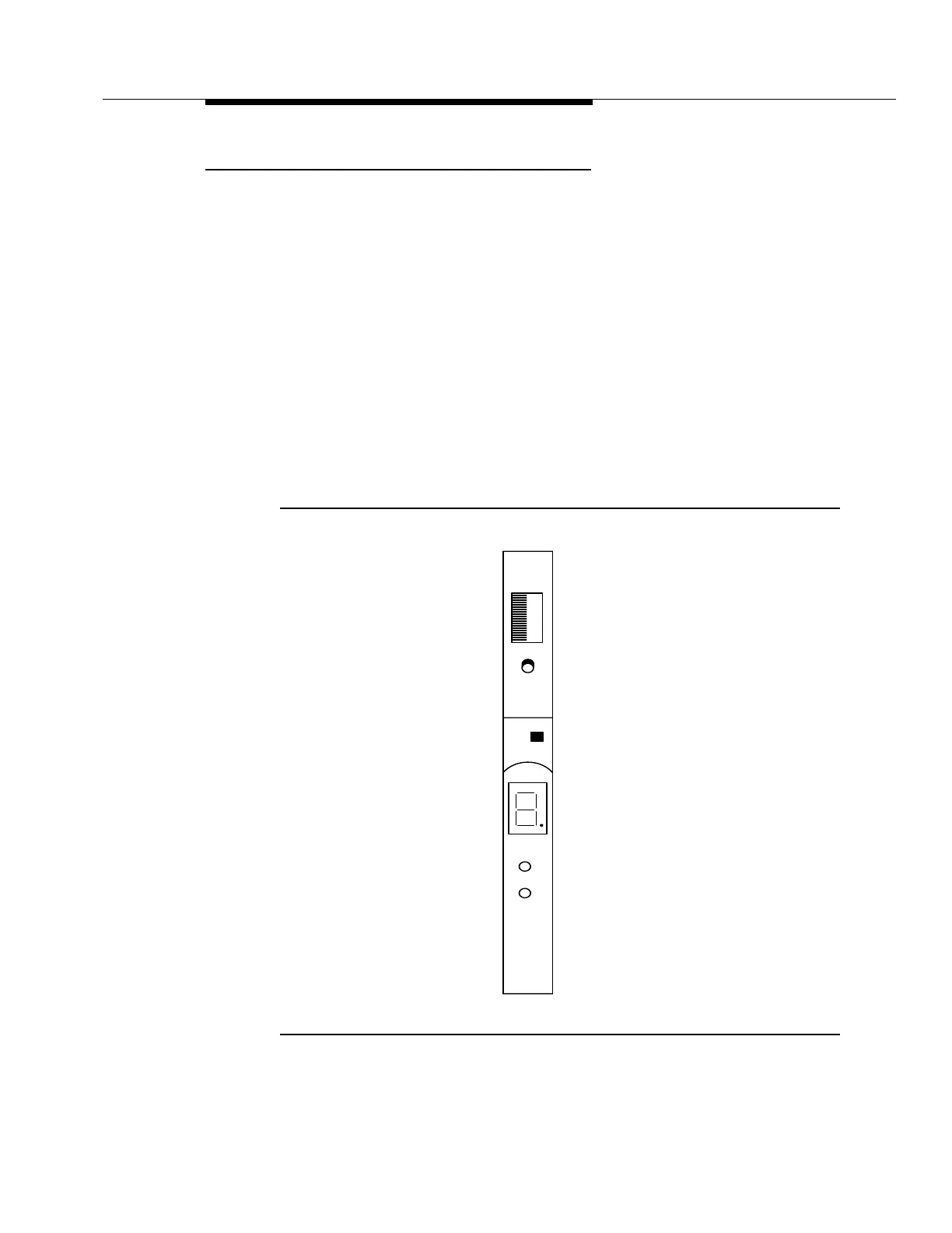
BBG8/BBG8B SYSCTL Faceplate Controls and
Indicators 7
The BBG8/BBG8B SYSCTL circuit pack faceplate controls and indicators are
shown in Figure 7-2. The SYSCTL has a red FAULT LED and a 7-segment
numeric LED display, as well as the FE SEL and UPD/INIT pushbuttons on its
faceplate. The red FAULT LED lights on detection of a circuit pack failure.
Figure 7-2. BBG8/BBG8B SYSCTL Circuit Pack
SYSCTL
BBG8B
x
x
x
S1:1
x
x
Lucent
FAULT
UPD/INIT
FE SEL
FE ID