363-206-295
Circuit Pack Descriptions
7-32 Issue 1 December 1997
BBG11B 3DS3 Circuit Pack Description 7
Purpose of Circuit 7
The BBG11B 3DS3 circuit pack provides a low-speed interface between
asynchronous DS3 rate signals and SONET standard STS-1 signals. The
BBG11B provides the same functions as the BBG11 and can be used in place of
the BBG11 in all applications. In addition, the BBG11B provides enhanced DS3
PM.
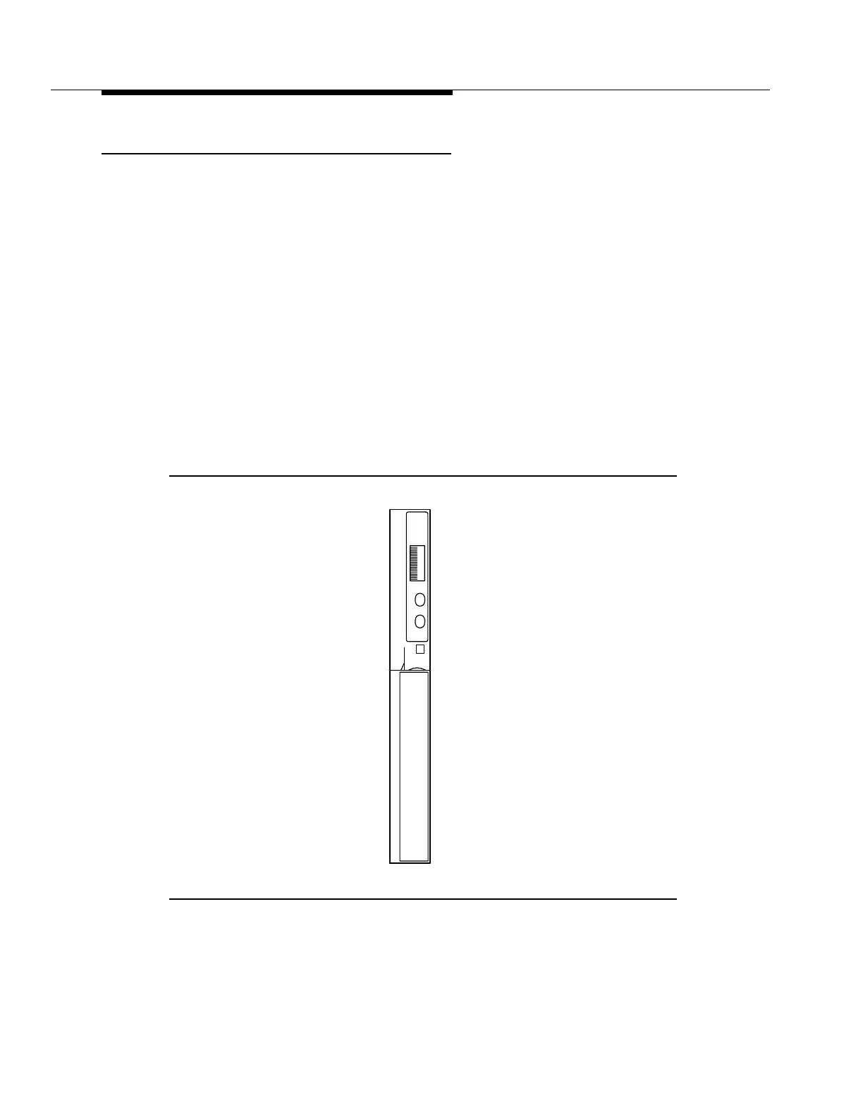
BBG11B 3DS3 Faceplate Indicators 7
The BBG11B 3DS3 circuit pack faceplate indicators are shown in Figure 7-13.
The red FAULT LED is lit by the SYSCTL on detection of the BBG11B 3DS3 circuit
pack failure or by the loss of the circuit pack +5 V DC. In the event of an incoming
signal failure, this LED will flash on and off. The green ACTIVE LED lights when
the circuit pack is active (carrying service).
Figure 7-13. BBG11B 3DS3 Circuit Pack
x
x
BBG11
x
x
x
LUAF
CVITA
3DS3
T
S1:1
Lucent
E