363-206-295
Circuit Pack Descriptions
7-66 Issue 1 December 1997
Detailed Description of Operation 7
Transmission Circuitry 7
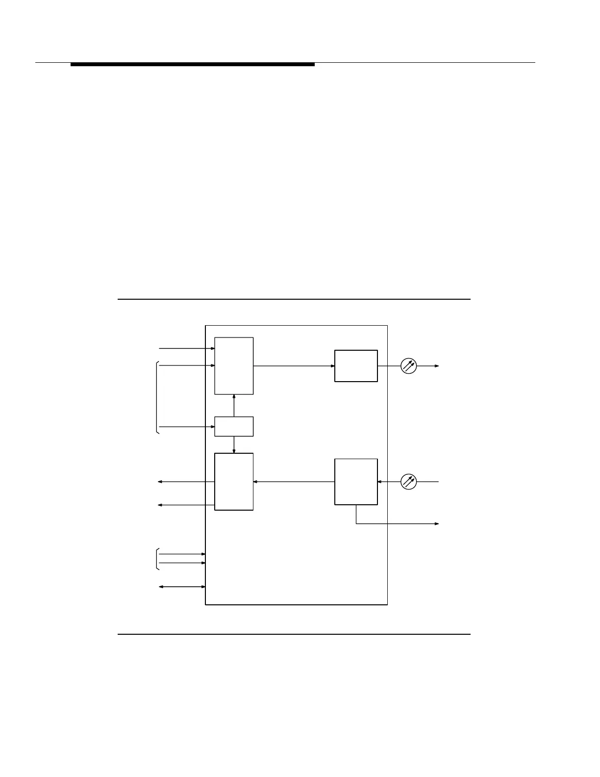
Transmit Direction. 7Figure 7-27 is a functional block diagram of the 23G/23G-U
OLIU. The 23G/23G-U OLIU receives an STS-1 rate clock and an associated
frame pulse from each of the working and standby TSI circuit packs. The 23G/
23G-U OLIU, under control of the SYSCTL, normally selects signals from the
working TSI. If a failure of the working clock is detected, the 23G/23G-U OLIU can
be switched to the standby TSI under SYSCTL control. An STS-12 rate clock is
generated from the STS-1 clock and used in creating the STS-12 signal. Under
control of the SYSCTL circuit pack, the 23G/23G-U OLIU selects one group of 12
STS-1 signals from either of the 12 active or 12 standby STS-1 inputs. The 23G/
23G-U OLIU performs pointer processing and frame alignment, and adds
transport overhead to the selected STS-1 signals. The 23G/23G-U OLIU provides
access to the transport overhead which is sent to and received from the OHCTL.
Figure 7-27. 23G/23G-U OLIU Circuit Pack Block Diagram
To
Rx Fiber
To
From
OHCTL CP
TSI CPs
From
OHCTL CP
-48V Fuses
From Shelf
SYSCTL CP
To/From
(Service &
(Service &
TSI CPs
TGS CP
Tx Fiber
Receive
Timing
Clock & Frame
DEMUX
Pointer
SONET O/H
and
MUX
Protection)
Protection)
Control
Intrashelf
Recovery
Timing
Electrical
Optical/
Convert
To
Optical
Electrical/
OC-12
OC-12
+
-48V (B)
-48 (A)
SONET O/H
12 STS-1s
STS-12 Signal
Timing
Processor
Pointer
and
12 STS-1s STS-12 Signal
Processor