Snug up locking nut by turning tool
clockwise (± 4 turns).
mmo2008-003-044_b
TURN TOOL CLOCKWISE
Reinstall belt guard.
Close LH side panel.
Drive Belt Height Adjustment
(Screw Type Adjuster)
The drive belt height adjustment must
be performed every time a new belt is
installed.
To adjust the drive belt height, proceed
as follo ws:
– Remove DESS key from post.
– Open LH side panel, refer to BODY.
– Remove belt guard, refer to DRIVE
BELT GUARD REMOVAL.
– Keep the set screws from turnin g
usinga3mmAllenkeyandloosen
both lock nuts using a 10 mm open
wrench.
LOOSEN THE LOCK NUTS
1. 3 mm Allen key
2. 1 0 mm open wrench
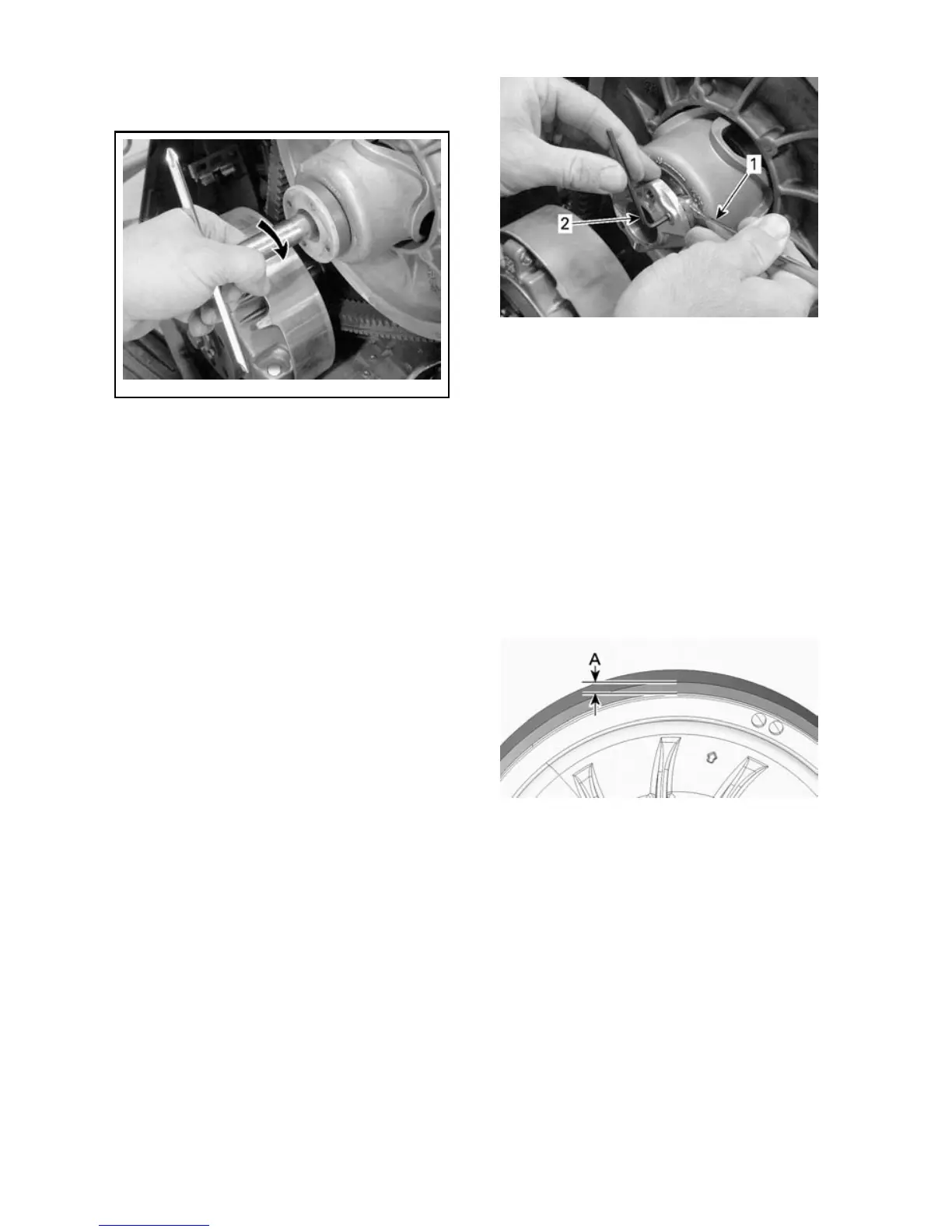
– Turn the set screw 1/ 4 turn at a
time then ro tate t he driven pulley to
properly set the belt between the
pulley sheaves. Repeat until the
top of drive belt reaches the driv-
en pulley edge, not exceeding 1mm
(0.039in).
NOTE: Turning the set screws clock-
wise lowers the belt in the pu lle y.
Turning the set screws counterclock-
wise raises the belt in the pulley.
A. 1mm (.039 in) maximum
– Set the other set screw so that it
rests on the steel ring.
108
_____________________