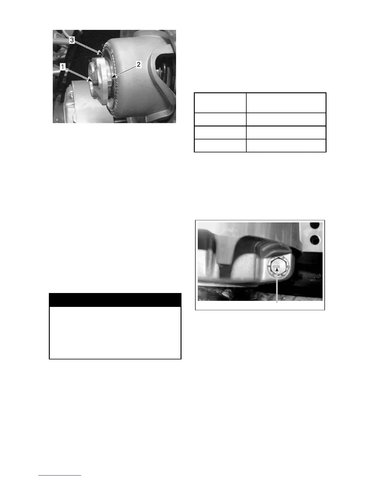
1. Set screw
2. Lock nut
3. Steel ring
– Keep the set screws from turn-
ing and tighten the lock nuts to-
wards the adjuster hub to 5 N•m
(44 lbf•in)
– Install belt g uard, refer to DRIVE
BELT GUARD INSTALLATION.
– Close side panel, refer to BODY.
If the vehicle creeps, lower the belt,
install the belt guard an d side pane l,
then start engine. Repeat until creep-
ing stops.
NOTE: If it is impo ssible to reach the
proper adjustment, c ontact an autho-
rized LYNX dealer.
Drive Pulley Adjustment
WARNING
Remove the tether cord cap (DESS
key) before performing any main-
tenance or adjustment, unless oth-
erwise specified. Vehicle m ust be
parkedinasafeplace,awayfrom
the trail.
General
The drive pulley is factory calib rate d t o
transmit maximum engine power at a
predefined RPM. Factors such as am-
bient temperature, altitude or surface
condition may vary this critical engine
RPM thus affecting snowmobile effi-
ciency.
This adjustable drive pulley allows set-
ting maximum engine RPM to main-
tain maximum power.
Calibratio n screws sh ou ld be adjuste d
so that actua l maximum engine RPM
matches the maximum horsepower
RPM.
ENGINE
MAXIMUM
HORSEPOWER RPM
593SS
8000 RPM (± 100)
600 HO E-TEC
8100 RPM (± 100)
800R 8150 RPM (± 100)
NOTE: Use precision digital tachome-
ter for engine RPM adjustment.
NOTE: The adjustment has an effect
on high RPM only.
Calibrat ion screw has a notch on top
of its head.
1
A33D19A
TYPICAL
1. Notch
There are 6 positions numbered 1 to 6.
Each position modifies maximum en-
gine RPM by about 200 RPM.
Lower position numbers decrease en-
gine RPM in steps of 200 RPM and
higher position numbers increase it in
steps of 200 RPM.
Example:
Calibration screw is set at position
4andischangedtoposition6. So
maximum engine RPM is increased
by 400 RPM.
_____________________
109