UNLOADING & ASSEMBLY
ATTACH HYDRAULICS AND ELECTRICAL (continued)
4. Attach malor
to
header primary drive:
a)
Complete
the
following steps
to
increase
clearanc
e for
motor
ins
ta
llat
ion:
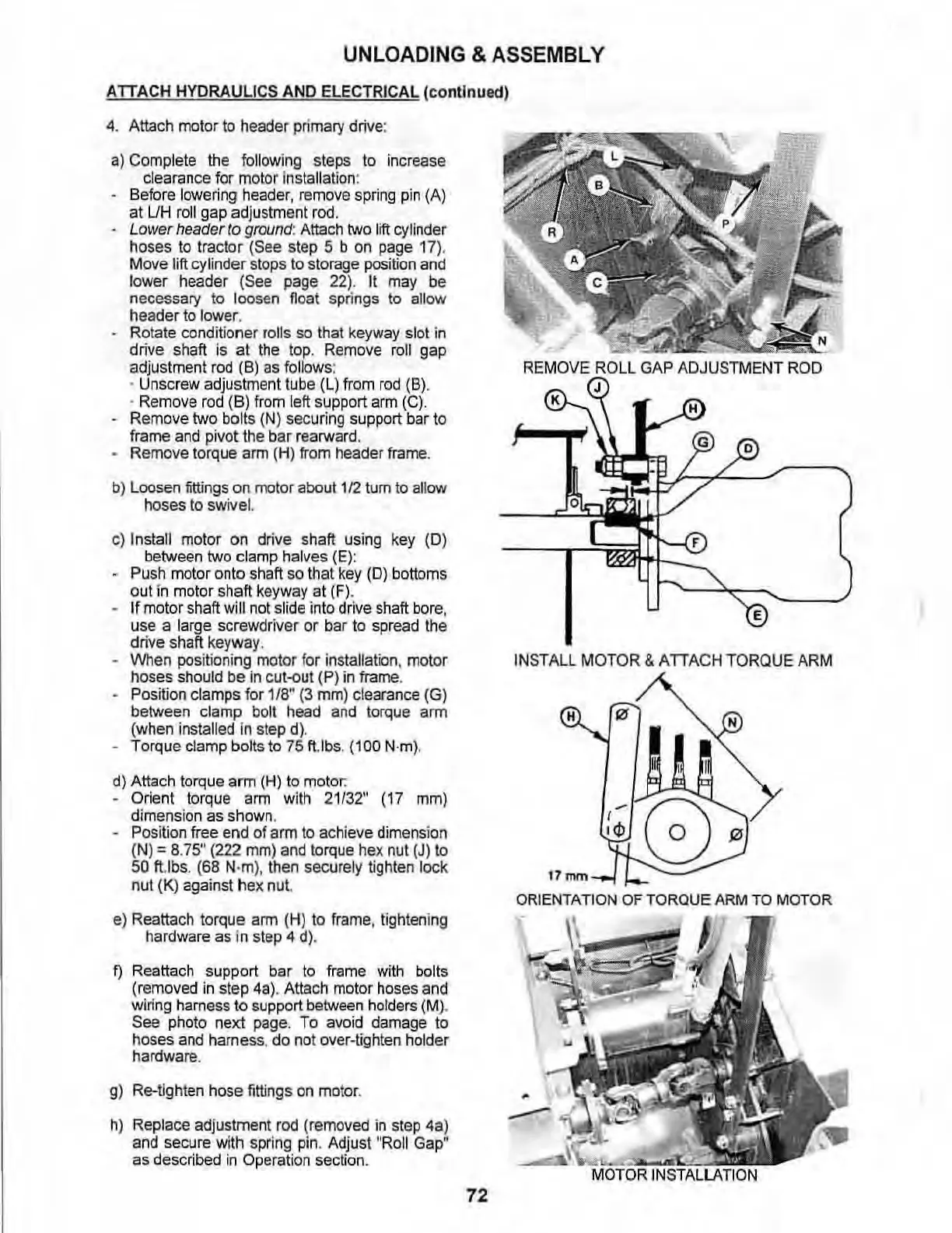
Before
low
ering
header,
remove
sp
r
ing
pin
(A)
at
UH
roll
gap
ad
justment
rod
.
Lower header
to
ground
:
Attach
two
lift
r:yJinder
hoses
to
tractor (See step 5 b
on
page
17
).
Move
lift
cyli
nde
r st
ops
to storage
position
and
lower
hea
de
r
(See
page
22)
. It
may
be
necessary to l
oosen
fl
oat sprin
gs
to allow
he
ader to lower.
Rotate conditioner
rolis
so
that
keyway
sl
ot
in
drive
sha
ft
is at the
to
p.
Rem
ove
roll
gap
adjustment
rod
(B)
as
follows:
•
Unscrew adjustment tube (L)
from
rod
(8) .
. Remove
rod
(8) f
rom
left s
upp
ort
arm
(e).
Remove
two
bo
l
ts
(N) securing support bar to
frame
and
pivot
the
bar r
earwa
rd
,
Remove torque
arm
(H)
from
header
frame
.
b)
Loosen
fittings
on
motor about 1
12
tum
to
aliO'N
ho
ses
to swivel.
c)
Install motor
on
drive shaft
using
key
(0)
between
two
clamp halves
(E):
Push
motor onto shaft
so
that
key
(0)
bott
oms
out
in
motor sha
ft
keyway
at
(Fl.
If motor shaft will
not
s
lide
int
o drive
shaft
bore
,
use a large screwdriver or bar
to
spread
the
drive shaft
keyway
.
\Nhen
pos
it
io
ni
ng
motor
fo
r
in
stall
ation.
motor
hoses
shou
ld
be
in
cut~ut
(P) in frame.
Po
sition cl
amps
fo
r 1/8" (3
mm)
c
le
arance
(G)
between clamp
bol
t
head
and
torque
arm
(when installed In step d).
Torque clamp b
olts
to
75
fUbs. (100 N·m
).
d) Attach torque arm (H) to
moto
r:
Orient torque
arm
with
21/32"
(17
mm)
di
mens
i
on
as
shown.
Pos
iti
on
free
end
of
arm
to
achieve
dimens
ion
(
N)
= 8.75" (222
mm)
and
lorque
hex
n
ut
(J)
10
50 ft.lbs.
(68
N·m). then securely tighlen l
oc
k
nut
(K)
against hex
nu
t.
e)
Reattach torque
arm
(H)
to
frame
,
tigh
t
en
i
ng
hardware
as
in st
ep
4 d),
f)
Reattach support bar
to
frame
with
bolts
(removed
in
step 4
a)
. Attach
motor
hose
s
and
wiri
ng
hame
ss
to
su
pport
between
h
olders
(M)
.
See photo next
page
. To
avoid
damage
to
hoses
and
hame
ss
, do
no
t over-tighten holder
hardware.
g)
Re-tighten hose fittings
on
mo
tor.
h) Replace
ad
justment
rod
(removed
in
step
4a
)
and
secure with
spring
pin
. Adjust
"Roll
Gap
H
as
described
in
Operation section.
72
REMOVE
ROLL
GAP
ADJUSTMENT
ROD
o
E
I
NSTALL
MOTOR & ATTACH T
ORQU
E
ARM
H
(l/
17mm
OR
IE
NTATION
OF
TORQUE
ARM
TO
MOTOR