2 - HYDRAULIC ATTACHMENT AND MANUAL LOCK
ENGAGING THE ATTACHMENT
- Check that the attachment is in a position which simplifies the connection to the
carriage. If it is badly positioned, take all the necessary precautions to move it safely.
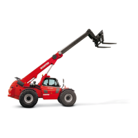
- Check that the locking pin is engaged in the support (Fig. A).
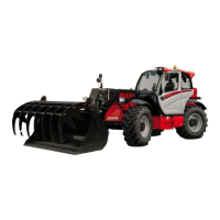
- Place the telehandler with the boom lowered in front of and parallel to the attachment
and tilt the carriage forward (Fig. B).
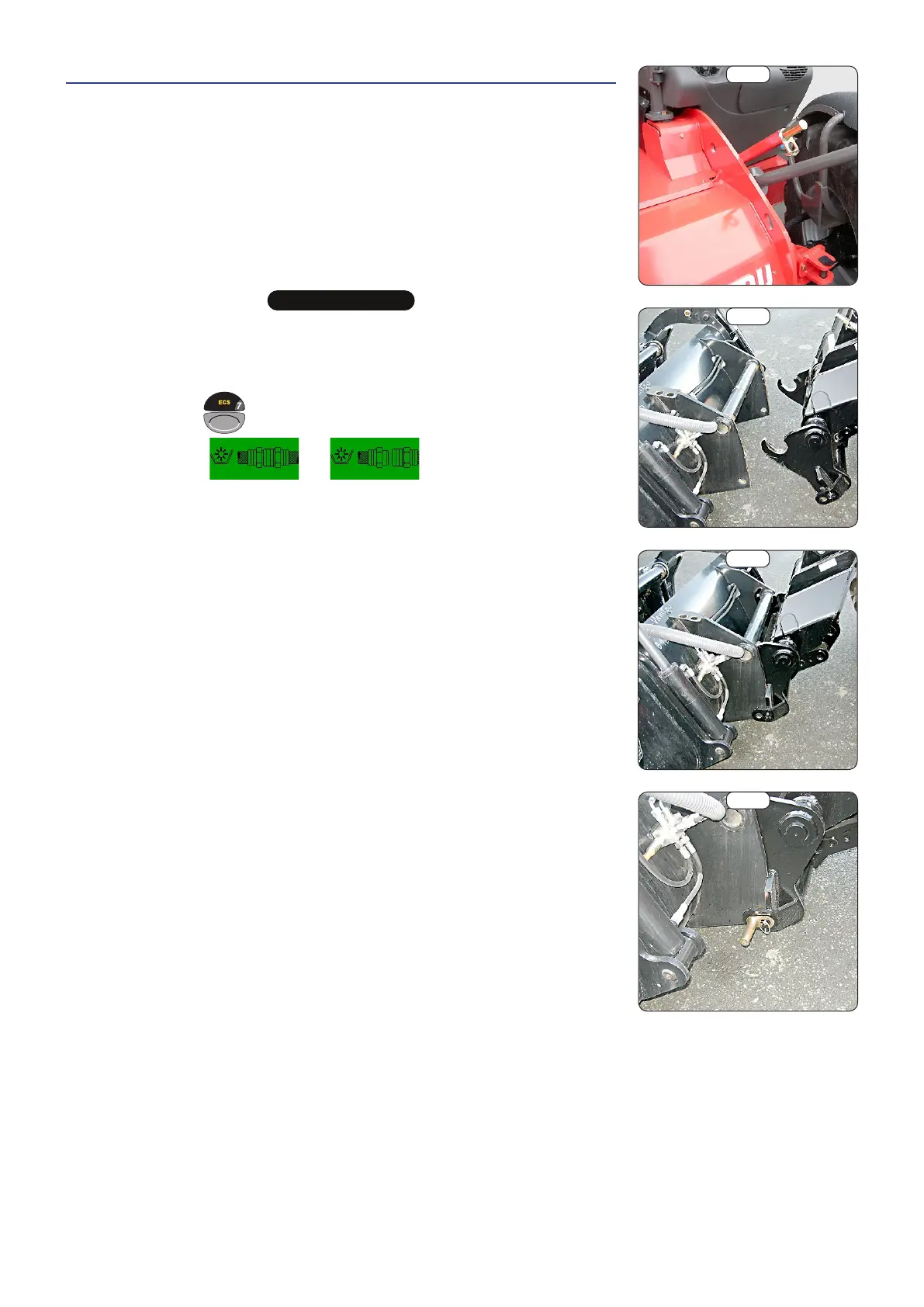
- Take the carriage under the connection pipe of the attachment, slightly raise the
boom and tilt the carriage back in order to position the attachment (Fig. C).
- Raise the attachment off the ground for easier engagement.
MANUAL LOCKING AND CONNECTION OF THE ATTACHMENT
d
IMPORTANT
d
Check the quick couplings for cleanliness and protect the unused orifices with the caps provided.
- Take the locking pin from the support (Fig. A) and lock the attachment in place
(Fig. D). Do not forget to fit on the split pin.
- Turn off the I.C. engine and keep the telehandler ignition on.
- Press the button
for two seconds to release the attachment circuit hydraulic
pressure. screens
and will be alternately displayed.
- Connect the quick couplings, respecting the logic of the hydraulic movements of
the attachment.
MANUAL RELEASE AND DISCONNECTION OF THE ATTACHMENT
- Follow the MANUAL LOCKING AND CONNECTION OF THE ATTACHMENT procedure
in reverse order, taking care to replace the locking pin in its support (Fig. A).
LAYING THE ATTACHMENT
- Follow the ENGAGING THE ATTACHMENT procedure in reverse order, taking care
to lay the attachment flat on the ground and in closed position.
A
B
C
D
7
 Loading...