18000 SERIVCE/MAINTENANCE MANUAL HYDRAULIC SYSTEM
Manitowoc Published 12-05-17, Control # 035-23 2-21
• Drum 4 (Boom Hoist)
• Drum 5 (Mast Hoist)
• Drum 6 (Luffing Jib Hoist)
• Swing (left and right)
• Travel (left and right)
4. Each system must show some charge pressure within
30 seconds of starting engine.
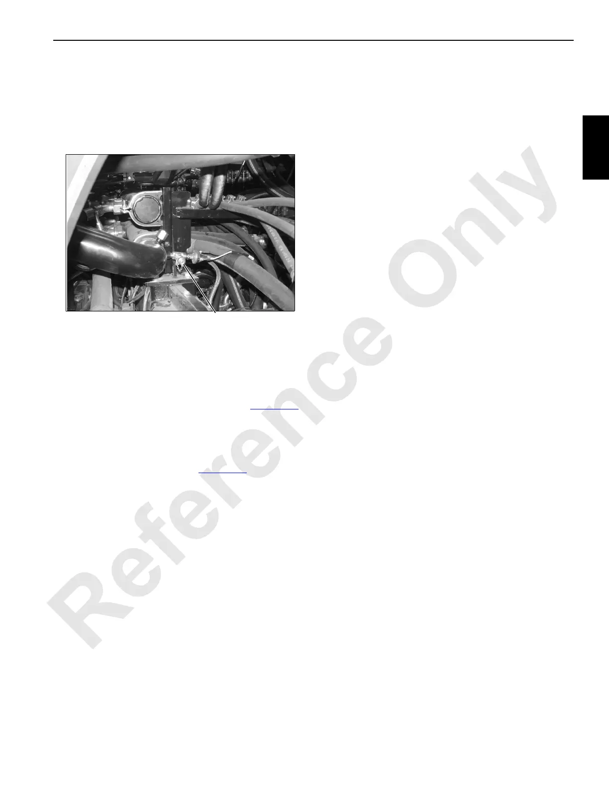
5. Observe gauge pressure at test port (Figure 2-18
).
Pressure must be between 75-100 psi (5-7 bar).
6. Stop engine.
7. Contact Engineering Department if any pump fails test.
8. Remove gauge from test port (Figure 2-18
).
Control Calibration
Calibrate the pump controls as instructed in this section.
Hoist Pumps Pressure Test
Test the pressure of the hoist pumps as instructed in this
section.
Travel Pressure Check
1. With brake on, move crawler handles in both directions
to stroke travel motors.
2. Travel screen pressure should be 4,500 psi (303 bar).
3. Travel brakes must hold without slipping.
Swing Pressure Check
1. With brake on, move swing handle in both directions to
stroke swing motor.
2. Swing screen pressure should be 4,500 psi (303 bar).
3. Swing brake must hold without slipping.
Accessory System Checks
High Pressure Accessory System
The accessory pumps are the source for high pressure
accessories. High pressure accessories include rotating bed
jacking cylinders, front and rear adapter frame pins, cab tilt
cylinder, mast pin cylinders, boom hinge pin cylinders, mast
raising cylinders, and rigging winch. For operating these
items, select and confirm SETUP REMOTE mode.
1. Rotating bed jacking cylinders:
a. Access hand-held radio remote control.
b. Use jack toggles to fully extend jacks.
c. Scroll to accessory screen on diagnostic screen to
verify that 3,000 psi (206 bar) is present when
cylinders are extended and retracted.
d. When retracting jacks, the rotating bed must lower
slowly and smoothly.
2. Front and rear adapter frame pin cylinders:
a. Remove locking plate to allow pin cylinders to
operate.
b. Access hand-held radio remote control.
c. Use front or rear toggles to ENGAGE and
DISENGAGE cylinders several times and remove
air from system.
d. Scroll to accessory screen to verify that 3,000 psi
(206 bar) is present when cylinders are engaged
and disengaged.
3. Cab tilt cylinder:
a. Access cab tilt control on front console in operator’s
cab.
b. Use rocker switch to ENGAGE and DISENGAGE
cylinder several times and remove air from system.
c. Scroll to accessory screen to verify that 3,000 psi
(206 bar) is present when cylinder is engaged and
disengaged.
4. Mast pin cylinders:
a. Remove keeper plate to allow pin cylinders to
operate.
b. Access hand-held radio remote control.
c. Use mast pins toggle to ENGAGE and
DISENGAGE cylinders several times and remove
air from system.
d. Scroll to accessory screen to verify that 3,000 psi
(206 bar) is present when cylinders are engaged
and disengaged.
Connect Charge Pressure
Gauge Here
Opening in Right Side
of Rotating Bed
FIGURE 2-18

 Loading...


