ELECTRIC SYSTEM 18000 SERIVCE/MAINTENANCE MANUAL
3-34
Published 12-05-17, Control # 035-23
DIGITAL DISPLAY
The digital display and scroll up/down rocker (see Special
Controls in this section) allow the operator to monitor
operating conditions screen, operating limits screen, or
system faults screen.
To display one of the above screens, depress the top or
bottom of the digital display screen selector to scroll up or
down through the display readings. Continue to scroll up or
down until desired screen is displayed.
Crane Operating Conditions
Table 3-5 lists operating conditions that are displayed and
the normal operating range of each item. The current status
of operating conditions are displayed in the screen shown in
Figure 3-6
.
The engine screen (Figure 3-7
) displays the following
information.
The engine diagnostics screen (Figure 3-8
) displays engine
faults. See Engine Diagnostics in section 7 of this manual for
information on fault codes.
The mast angle, battery voltage, and crane level screen
(Figure 3-9
) displays the following information.
On crane Serial Numbers 18001081 and older, the wind
speed and pump drive screen (Figure 3-10
) displays the
current steady wind speed, maximum gust wind speed, and
pump drive operating conditions.
• MAX WIND SPEED resets when crane power is off.
Pump drive operating conditions are provided only on
current production cranes (pump drives with a circulating oil
system).
On crane Serial Number 18001082 and newer, the hydraulic
tank fluid level, wind speed, and pump drive screen
(Figure 3-11
) displays the hydraulic tank fluid level, the
current steady wind speed or maximum gust wind speed (in
parenthesis, and pump drive operating conditions.
• For hydraulic tank level: 0% = empty; 100% = full cold;
110% is full hot
• MAX WIND SPEED resets when crane power is off
Operating Limits
Table 3-6 lists operating limits which can be displayed.
When one or more operating limit is reached, the operating
limit alert (yellow light and buzzer in cab) turns on to warn the
operator. Scroll to the crane faults/limits display screen. The
crane faults/limits screen (Figure 3-12
) automatically scrolls
through the active faults/limits, stopping at each for
approximately three seconds.
The operating limit alert turns off when the cause of limit is
corrected. Each active limit reached during operation is
retained in memory, until two things happen:
1. Name of limit appears on display at least once
2. Cause of limit is corrected
For this reason, it is normal for the inactive limits to appear
when you scroll to the operating limit group, even when the
operating limit alert is off.
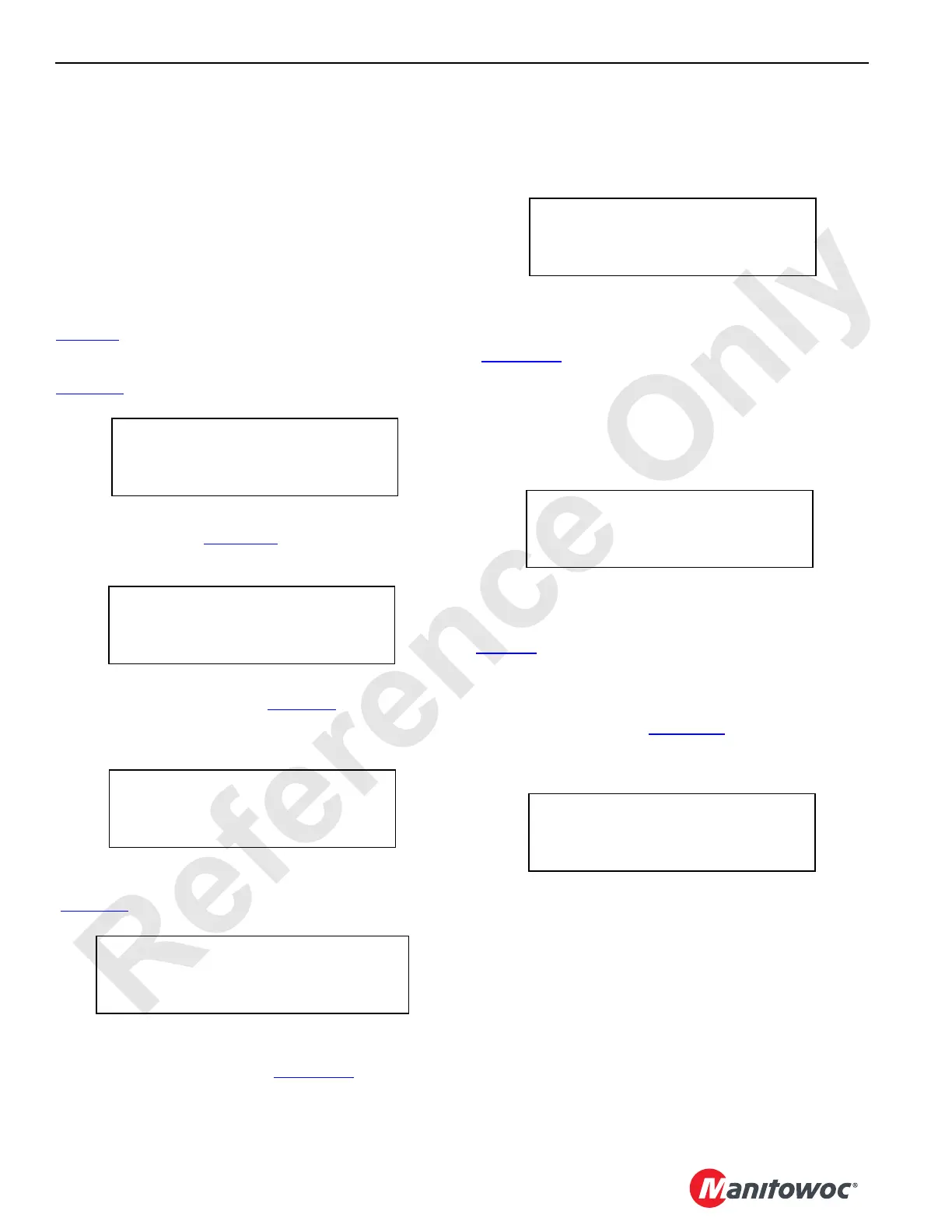
FIGURE 3-6
ENGINE SPEED 2,200 RPM
BOOM ANGLE 66. 0 DEG
LUFFING JIB ANGLE 00. 0 DEG
BOOM TO LUFF ANGLE 000.0 DEG
FUEL LEVEL 100%
OIL PRESSURE 50 PSI
COOLANT TEMP 150 DEG
ENGINE HOURS 1800
FIGURE 3-7
ENGINE DIAGNOSTICS
FLASH CODE - SPN- FMI-
FIGURE 3-8
MAST ANGLE DEG 000
BATTERY VOLTAGE V
TILT RIGHT DEG 000IN 00
TILT FRONT DEG 000 IN 00
FIGURE 3-9
CURRENT WIND SPEED 10 MPH
MAX WIND SPEED 20 MPH
PUMP DRIVE TEMP 160 DEG
PUMP DRIVE PRESSURE 25 PSI
FIGURE 3-10
HYD TANK FLUID LEVEL 100 %
CURRENT (MAX) WIND SPEED 20 MPH
PUMP DRIVE TEMP 160 DEG
PUMP DRIVE PRESSURE 25 PSI
FIGURE 3-11
CRANE FAULTS/LIMITS
OPERATING LIMIT- BLOCK UP
FIGURE 3-12

 Loading...


