UNDER CARRIAGE 18000 SERIVCE/MAINTENANCE MANUAL
8-4
Published 12-05-17, Control # 035-23
Adjustment Procedure
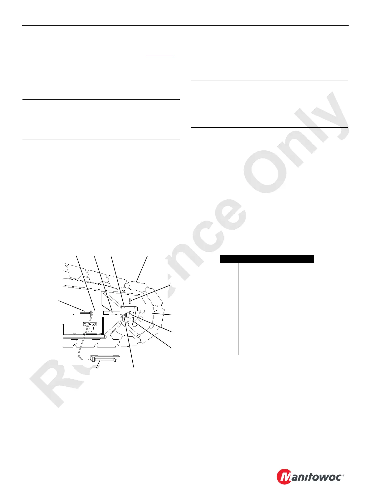
Adjust tread slack at roller end of each crawler (Figure 8-3).
1. Thoroughly clean crawler to be adjusted.
2. Loosen bolt on each side of crawler roller.
3. Remove cover from both sides of crawler frame.
4. Place jacking cylinders on supports on both sides of
crawler frame.
5. Jack against rod an equal amount on both sides of
crawler frame.
6. Add or remove an equal thickness of shims on both
sides of crawler frame.
7. Remove jacking cylinders.
8. Travel crane forward or reverse to tighten shims.
9. Check that dimension from center punch (A) in shaft to
center punch line (B) in crawler frame is same on both
sides of crawler to within 1/8 in (3 mm).
10. Check for proper adjustment (see Adjustment Guideline)
and readjust as required (steps 4 through 9).
11. Tighten nuts on bolts at crawler roller to 2,000 ft-lb
(2 710 Nm) lubricated with Never-Seez or an equivalent
oil and graphite mixture.
12. Install cover on both sides of crawler frame.
NOTE: The extreme limit of tread adjustment occurs when
the bolts are tight against the front end of the slots
in the crawler frame. One crawler tread can be
removed when this limit is reached.
CAUTION
Cylinder Damage!
Two jacking cylinders (one on each side of crawler frame)
are required to prevent damage to single jacking cylinder.
CAUTION
Part Wear!
Crawler roller and tumbler must be square with crawler
frame within 1/8 in (3 mm). Otherwise, parts will wear
rapidly.
FIGURE 8-3
Item Description
1 Hand Pump
2 Support
3 Jacking Cylinder
4Rod
5 Cover
6 Tread
7 Center Punch Line B
8 Crawler Roller
9 Center Punch A
10 Bolts
11 Shims
0.134 in (3 mm) and
0.250 in (6 mm) Thick
7
6
4
5
3
2
1
11
10
8
9
18CSM8-102
 Loading...


