ELECTRIC SYSTEM 18000 SERIVCE/MAINTENANCE MANUAL
3-4
Published 12-05-17, Control # 035-23
Pumps and Motors
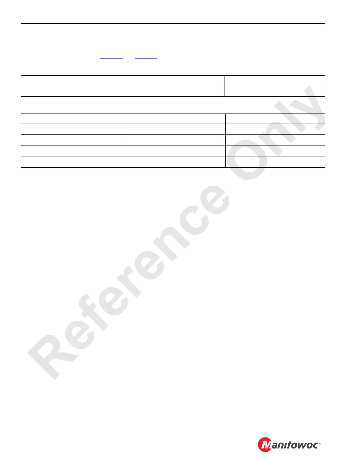
The node output voltage and input voltage values at the
pumps and motors are shown in Table 3-3
and Table 3-4.
Table 3-3. Pump Values
Table 3-4 Motor Values
1
Resistance increases as the temperature rises on the pump or motor control coil resulting in decreased current values (mA)
when measured with a meter. The listing in the table is the current range for a 21°C (70°F) coil.
2
Travel motor control is two speed. When the 2-speed travel motor control solenoid is energized, the motor is locked in max
displacement. When the motor control solenoid is de-energized, the pressure compensator will shift the motor to min
displacement. The Master Node will only de-energize the coil if the 2-Speed Travel Switch is in the high speed position and the
engine RPM is above 1500. The pressure compensator override will begin to shift motor back to max displacement, low speed
as the closed loop pressure reaches or exceeds 3915 to 4200 PSI (270 to 290 BAR) in order to stabilize and hold the pressure
constant protecting the motor from over heating and catastrophic failure.
At Node At Pump
All 0 to 24 Volts
0 to 2 Volts (0 - 95 mA)
1
At Node At Motor
Boom Hoist (Drum 4) 2.5 to 22 Volts
.2 to 2.2 Volts (10 to 90 mA)
1
Travel 0 or 24 Volts
0 or 24 Volts (0 or 1500 mA)
1,2
Hoist Drum 3 and 6 2.5 to 16 Volts
.2 to 1.6 Volts (10 to 65 mA)
1
Hoist Drum 1 and 2 2.5 to 19 volts
.2 to 1.9 volts (10 to 75 mA)
1
 Loading...


