ELECTRIC SYSTEM 18000 SERIVCE/MAINTENANCE MANUAL
3-44
Published 12-05-17, Control # 035-23
CAN (Can Bus)
The CAN screen displays digital inputs and outputs of the
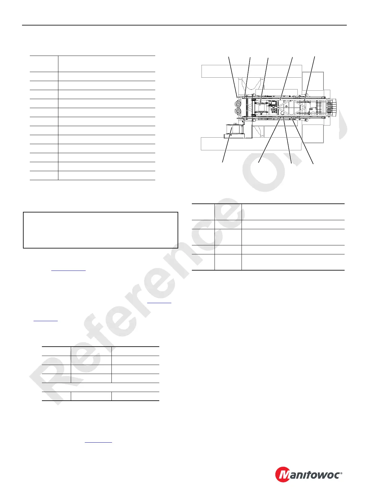
master node controller. The location of crane nodes are
shown in Figure 3-17
. The CAN screen displays the
following information:
• STATUS indicates possible active communication errors
between nodes on two banks that should read 000. The
binary system status numbers are shown in Table 3-9
.
If a communication error occurs (033 in bank one) see
Table 3-9
for bank identifier numbers (node-2 and node-
7)
Table 3-9
• HISTORY indicates errors since power was cycled.
Communication errors correspond to above table.
• BOOM indicates what boom nodes may be available on
the bus. Boom status should always display a number or
an error exists (see Table 3-10
).
Table 3-10
• ENGINE displays engine ECM bus status that is for
factory use only.
• W/L indicates what wireless receiver nodes can be
available.
- Number 1 is boom to load link.
- Number 2 is remote.
• PACKET ID number — Move select/confirm switch to
SELECT. Cursor appears next to Packet ID #. Scroll up
or down to desired packet number to display packet item
status.
• Digital input or digital output BANKS 1, 2, 3, and 4.
• Digital input or digital output BANKS 5, 6, 7, and 8.
Each individual input/output is assigned a number (identifier)
in the binary system (powers of two). The identifiers of all
inputs/outputs that are ON (active) for each bank are added
for a total of 0 – 255. The number displayed for each bank is
the sum of all identifiers that are ON in that bank. Each
possible ON/OFF combination per bank has a unique total.
FIGURE 3-17
Node
Number
Node
1 Master (Front Console)
2 Handles and Cab Controls
3 Drum 3 and Pressure Senders
4 Jacking, Connecting Pins, and Mast
5 Alarms, Limits and Pump Controls
6 Drums 2, 4, 5 & Adapter Frame Pins
7 Swing and Auto Lube
8 Drum 1 and Drum 6
9 MAX-ER (optional)
0 Engine
20 Boom Top (not shown)
21 Luffing or Fixed Jib Top (not shown)
In Right Side
Cab Console.
In Boom Butt
In Boom
Top or Jib
2
3
4
9
5
6
7
8
21
20
0
BIN Node
1
18CSM3-103
STATUS 033
*PACKET ID #
BANKS 1 - 4:
BANKS 5 - 8:
000
38
55
4
HIST
0
35
000 000
BOOM 16
178 0
0 16
ENG
W/L
12
1
CAN
Bank 1 1 = Node 2 16 = Node 6
2 = Node 3 32 = Node 7
4 = Node 4 64 = Node 8
8 = Node 5 128 = Node 0
Bank 2 1 = Node 9 2= BIN Node
Boom
Status
Node
Number
Description
1 21 Luffing Jib node with #44
821
Luffing jib node 79A or
Fixed jib node 79A
16 20 Boom top node 55A or 79A
128 20 or 21
Indicates a node is present that is not
currently identified.
 Loading...


