18000 SERIVCE/MAINTENANCE MANUAL HYDRAULIC SYSTEM
Manitowoc Published 12-05-17, Control # 035-23 2-37
Charge Pressure Adjustment
The following adjustment is only required when a system
fails the Charge Pressure Test described in this section.
1. Scroll to system display screen for corresponding
function.
2. Start and run engine at high idle. With function in neutral,
system pressure on diagnostic screen should read 320
to 370 psi (22 to 25,5 bar).
3. If specified pressure is not indicated, stop engine and
connect an accurate 0 to 1,000 psi (0 to 69 bar)
hydraulic pressure gauge to coupler at corresponding
pressure sender.
4. Repeat step 2
, if specified pressure is still not indicated:
• Do a Pressure Sender Test as instructed in this
section. Replace faulty pressure sender if needed.
• Do a Control Calibration as instructed in this
section.
If specified pressure is still not indicated:
• If pressure is too high, check that pump neutral is
adjusted properly. If pressure is still high, adjust
charge pressure relief valve.
• If pressure is too high, adjust charge pressure relief
valve. If you cannot raise charge pressure,
excessive system leakage is indicated.
5. To adjust charge pressure:
See Figure 2-29
for the following procedure.
a. Loosen lock nut (1).
b. Adjust adjusting plug (2).
- Turn in to increase pressure.
- Turn out to decrease pressure.
c. Once specified pressure is indicated, hold adjusting
plug (2) in position and securely tighten lock nut (1).
6. Stop engine and remove gauge from gauge port.
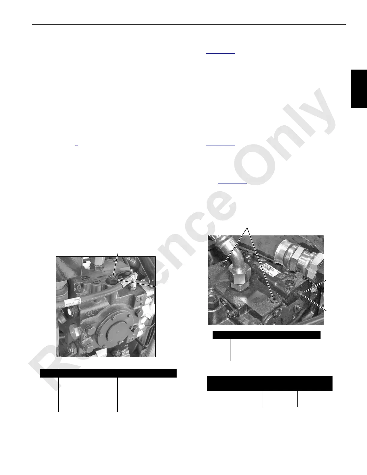
Pump Neutral Adjustment
See Figure 2-30 for the following procedure.
To adjust pump neutral:
1. Park all crane functions and stop engine.
2. Disconnect electrical (DIN) connector from pump EDC
(see Figure 2-32
).
3. Install an accurate 0 to 1,000 psi (0 to 69 bar) hydraulic
pressure gauge in each servo gauge port (1).
4. Start and run engine at high idle.
Item Description Hex Wrench Size
1 Lock Nut 1/2 in (12,7 mm)
2
Adjusting Plug
Series 030-100
1-1/16 in (27,0 mm)
Adjusting Plug
Series 030-100
1-5/8 in (41,28 mm)
1
P1600a
FIGURE 2-29
2
Typical Pump Installation
1
2
Item Description
1 Servo Gauge Ports (SAE 06)
2 Lock Nut
3 Adjusting Screw
Wrench Size
Pump Series
Lock Nut
Hex Size
Internal
Hex Size
Early Series Units 17 mm 5 mm
Current Series Units 10 mm 3 mm
FIGURE 2-30
P1535a
Typical Pump Installation
3
 Loading...


