ELECTRIC SYSTEM 18000 SERIVCE/MAINTENANCE MANUAL
3-2
Published 12-05-17, Control # 035-23
CIRCUIT BREAKER IDENTIFICATION
This section contains circuit breaker identification. There are
no individual in-line fuses.
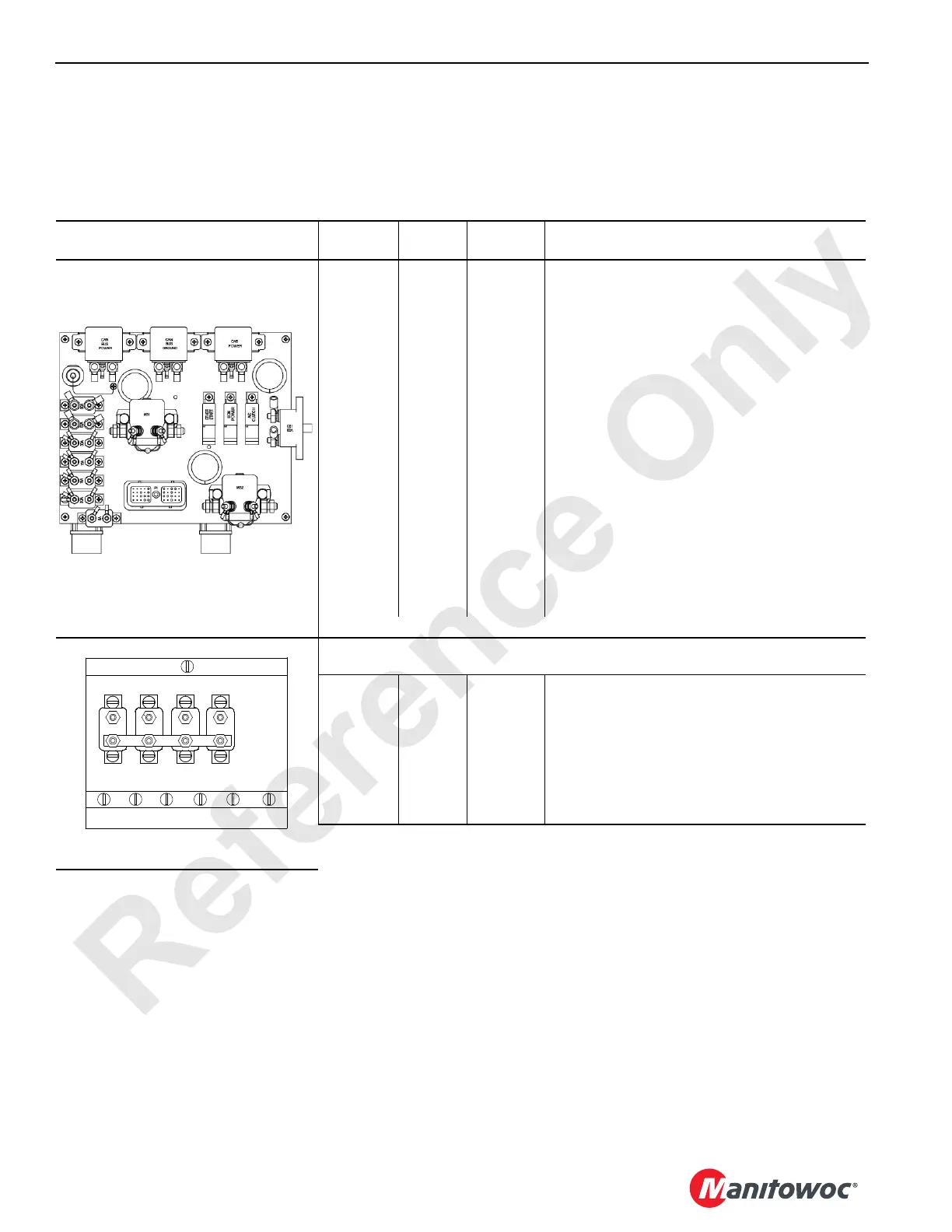
Circuit breakers CB-1 through CB-8 are mounted in the
engine node-0 controller box in left side enclosure.
Circuit breakers ABCB1 through ABCB4 are mounted in load
center of right hand console in operator’s cab.
Table 3-2 Circuit Breaker Identification
Circuit Breaker Location
Circuit
Breaker
Amps Wire No. Description of Items Protected
CB-1 60 6A Main System 24 Volt Power
CB-2 8 6C2 Electronic Control Module (Cummins)
CB-3* 10 6C6 Electronic Control Module (Cummins Tier 3)
CB-3* 30 6C6 Electronic Control Module (Cummins Tier 4)
CB-4 10 6C8 Engine Stop
CB-4 10 6C8 Engine Stop-Run-Start
CB-4 10 6C8 Dome Light
CB-4 10 6C8 Horn
CB-4 10 6C8 Radio
CB-5 15 6C11 Ether Start
CB-5 15 6C11 Air Conditioner Clutch
CB-5 15 6C11 Heater/Air Conditioner Compressor
CB-6 30 6C12 Start Solenoid
CB-7 50 6C13 Can Buss Power
CB-7 50 6C13 Master Node 1 Power
CB-7 50 6C13 Operating Controls
CB-8 50 6C14 Cap Power
* 10 amps Tier 3 or 30 amps Tier 4 (reference crane electrical schematic)
A8CB1 25 8PW 24/12 Volt Converter
A8CB2 15 8HP Air Conditioning/Heater Power
A8CB3 15
8WF
8WO
Front Wiper
Overhead Wiper
A8CB4 8 8P Panel Lights
Left Side Enclosure Near Engine
81015969
A8CB4
8A 15A 15A
25A
In Load Center
(Bottom of Right Console)
A8CB3 A8CB2 A8CB1
18CSM3-100
 Loading...


