HYDRAULIC SYSTEM 18000 SERIVCE/MAINTENANCE MANUAL
2-22 Published 12-05-17, Control # 035-23
5. Boom hinge pin cylinders:
NOTE: Hydraulics must be connected to boom butt to
operate boom hinge pin cylinders.
a. Remove lock plate to allow hinge pin cylinders to
operate.
b. Access hand-held radio remote control.
c. Use boom hinge pins toggle to ENGAGE and
DISENGAGE cylinders several times and remove
air from system.
d. Scroll to accessory screen to verify that 3,000 psi
(206 bar) is present when cylinders are engaged
and disengaged.
6. Mast raising cylinders:
a. Access hand-held radio remote control.
b. Use mast toggle to RAISE and LOWER mast
cylinders several times to remove air from system.
c. Scroll to accessory screen to verify that 3,000 psi
(206 bar) is present when cylinders are retracted or
extended.
7. Rigging winch motor (optional):
NOTE: Hydraulics must be connected to boom butt and
boom inserts to operate rigging winch motor.
a. Access hand-held radio remote control.
b. Use payout and haul in toggle to PAYOUT and
HAUL IN several times to remove air from system.
c. Scroll to accessory screen to verify that 3,000 psi
(206 bar) is present when motor is operating.
Low-Pressure Accessory Components
The swing system pressure reducing shuttle valve is the low-
pressure source for the low-pressure accessories at a
pressure of 350 psi (24 bar). The low-pressure accessories
includes swing brake, swing lock, travel brake, and travel 2-
speed.
1. Swing brake and swing lock:
a. Scroll to swing diagnostic screen.
b. With swing park brake and swing lock OFF, attempt
to swing the crane by moving control handle in both
directions.
c. Crane must respond and indicate on swing screen
that swing park brake and swing lock are released.
2. Travel brakes:
a. Scroll to travel diagnostic screen.
b. With travel park brake OFF, attempt to travel the
crane by moving control handles in both directions.
c. Crane must respond and indicate on travel screen
that travel park brake is released.
3. Travel 2-speed is checked in test area when travel
speed is checked.
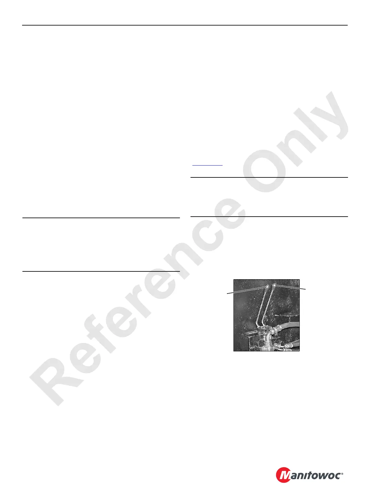
Lower Accessory Valve
The swing system pressure reducing valve is the low-
pressure source for operating the crawler pin handles
(Figure 2-19
) at pressure of 350 psi (24 bar).
d. With handles on front of carbody, fully extend the
crawler pins if they are not already extended.
e. Scroll to accessory screen to verify that a pressure
is present when pin cylinder are extended and
retracted.
CAUTION
Damage to Mast!
When raising mast for the first time or after maintenance
of mast cylinder, raise mast slowly and check that both
cylinders are raising mast evenly. Mast could twist if one
cylinder is not working correctly.
CAUTION
Machinery Damage!
Do not perform this test if crawlers are attached to
carbody.
P1927
FIGURE 2-19
Right Crawler
Pin Handle
Front of Carbody
Left Crawler
Pin Handle
 Loading...


