ELECTRIC SYSTEM 18000 SERIVCE/MAINTENANCE MANUAL
3-18
Published 12-05-17, Control # 035-23
NODE 6 - Drums 2, 4, & 5, and Adapter Frame
Reference Electrical Schematic A06374 - Sheets 10, 19, 20 and 21.
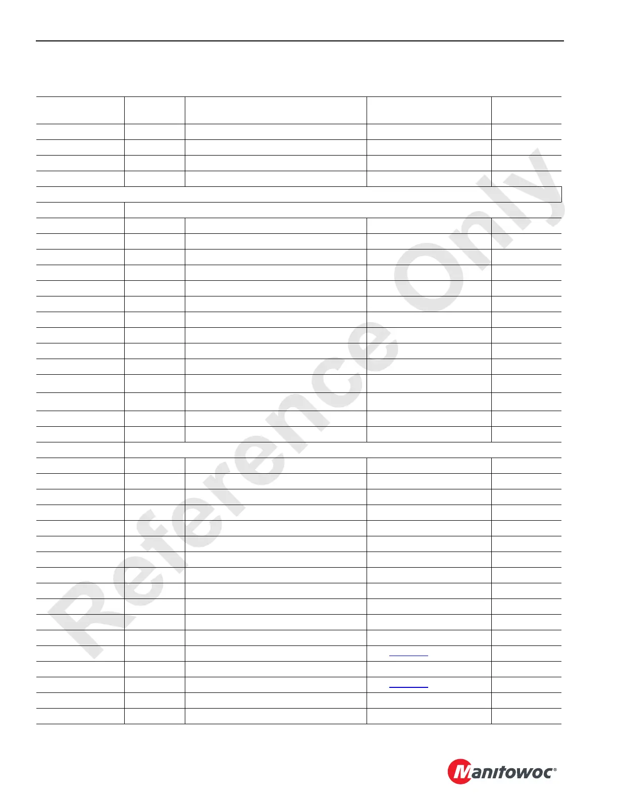
Can ID. No.
Function
Type
Description Test Voltages Packet No.
WN20-A/WNE06-A 24 Volts From Remote Receiver to Node 7 24 Volts Nominal
WN20-C/WNE06-C CANH Can High Wire Transmission N/A
WN20-D/WNE06-D Ground From Remote Receiver to Node 7 Ground
WN20-F/WNE06-F CANL Can Low Wire Transmission N/A
WN20 formerly WN18
J3 Receptacle – Drum 5 Controls
63-C Ground Drum 5 Brake Solenoid Ground
63-D DO-2 Drum 5 Brake Solenoid 0 Volts Off, 24 Volts On CAN34-1-2
63-E Ground Drum 5 Pawl Out Solenoid Ground
63-F DO-3 Drum 5 Pawl Out Solenoid 0 Volts Off, 24 Volts On CAN34-1-4
63-G Ground Drum 5 Pawl In Solenoid Ground
63-H DO-4 Drum 5 Pawl In Solenoid 0 Volts Off, 24 Volts On CAN34-1-8
63-J Ground Jumper to Node Select 1 Ground
63-K NS-1 Node Select 1 Jumper to Ground 0 Volts (With Jumper)
63-L NS-2 Node Select 2 Jumper to Ground 0 Volts (With Jumper)
63-N Ground Jumper to Node Select 2 Ground
63-a AI-1 Rotating Frame Level Sensor (Pitch) 0 to 10 Volts
CAN8-2
1
63-b AI-2 Rotating Frame Level Sensor (Roll) 0 to 10 Volts
CAN8-4
1
63-g Ground Rotating Frame Level Sensor Ground
63-j 5 Volts Rotating Frame Level Sensor 5 Volts DC
J4 Receptacle – Adapter Frame & Drum 4 Controls
64-A Ground Rear Adapter Frame Pins Engage Sol. Ground
64-B DO-11 Rear Adapter Frame Pins Engage Sol. 0 Volts Off; 24 Volts On CAN34-2-4
64-C Ground Rear Adapter Frame Pins Disengage Sol. Ground
64-D DO-12 Rear Adapter Frame Pins Disengage Sol. 0 Volts Off; 24 Volts On CAN34-2-8
64-E Ground Front Adapter Frame Pins Engage Sol. Ground
64-F DO-13 Front Adapter Frame Pins Engage Sol. 0 Volts Off; 24 Volts On CAN34-2-16
64-G Ground Front Adapter Frame Pins Disengage Sol. Ground
64-H DO-14 Front Adapter Frame Pins Disengage Sol. 0 Volts Off; 24 Volts On CAN34-2-32
64-U DO-19 Drum 4 Pawl In Motor 0 Volts Off; 24 Volts On CAN34-3-4
64-V Ground Drum 4 Pawl Motor Ground
64-W DO-20 Drum 4 Pawl Out Motor 0 Volts Off; 24 Volts On CAN34-3-8
64-X Ground Drum 4 Motor Control 1 Ground
64-Z DO-21 Drum 4 Motor Control 1 See Table 3-3
for Values CAN34-3-16
64-a Ground Drum 4 Motor Control 2 Ground
64-b DO-22 Drum 4 Motor Control 2 See Table 3-3
for Values CAN34-3-32
64-c Ground Drum 4 Brake Solenoid Ground
64-d DO-23 Drum 4 Brake Solenoid 0 Volts Off; 24 Volts On CAN34-3-64
 Loading...


