ELECTRIC SYSTEM 18000 SERIVCE/MAINTENANCE MANUAL
3-14
Published 12-05-17, Control # 035-23
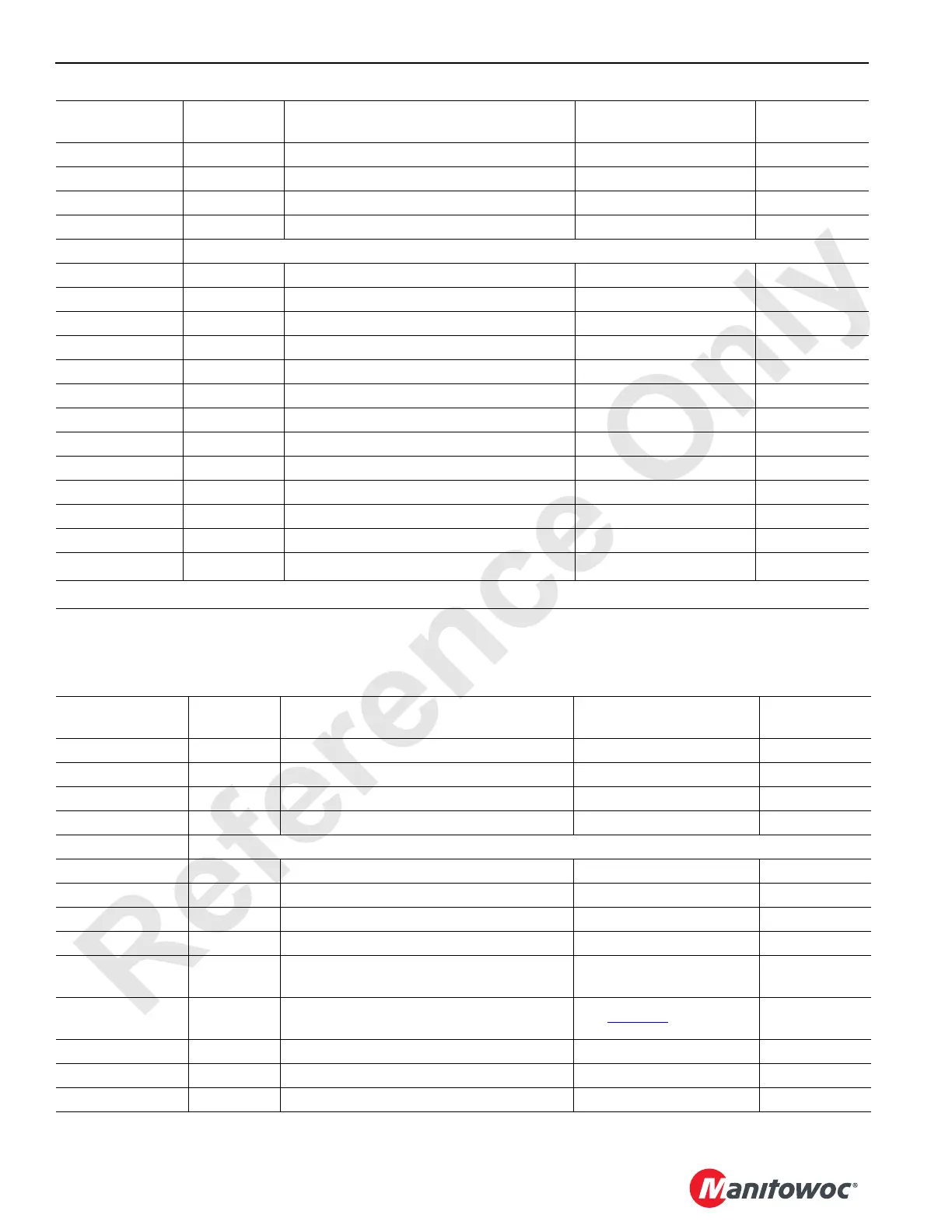
NODE 5 - Alarms, Pump Controls, and Limits
Reference Electrical Schematic A06374 - Sheets 9, 19, 20 and 21.
44-a Ground Left Rear Jack Retract Solenoid Ground
44-b DO-22 Left Rear Jack Retract Solenoid 0 Volts Off; 24 Volts On CAN35-3-32
44-g Ground Jumper to Node Select 3 Ground
44-k NS-3 Node Select 3 Jumper to Ground 0 Volts (With Jumper)
J6 Receptacle – Mast
46-A Ground Drum 3 Diverter Solenoid Ground
46-B DO-7 Drum 3 Diverter Solenoid 0 Volts Off; 24 Volts On CAN35-1-64
46-C Ground Drum 5 Diverter Solenoid Ground
46-D DO-8 Drum 5 Diverter Solenoid 0 Volts Off; 24 Volts On CAN35-1-128
46-E Ground Mast Raise Solenoid Ground
46-F DO-9 Mast Raise Solenoid 0 Volts Off; 24 Volts On CAN35-2-1
46-G Ground Mast Lower Solenoid Ground
46-H DO-10 Mast Lower Solenoid 0 Volts Off; 24 Volts On CAN35-2-2
46-M NS-3 Node Select 4 Jumper to Ground 0 Volts (With Jumper)
46-U Ground Jumper to Node Select 4 Ground
46-V 5 Volts Mast Angle Sensor 5 Volts
46-W Ground Mast Angle Sensor Ground
46-a AI-9 Mast Angle Sensor 5 Volts DC Mast at Vertical
CAN14-2
1
1
– Lower four bits are the most significant bit of the analog value.
Can ID. No.
Function
Type
Description Test Voltage Packet No.
WN16-A/WN14-A 24 Volts From Node 0 to Node 9 24 Volts Nominal
WN16-C/WN14-C CANH Can High Wire Transmission N/A
WN16-D/WN14-D Ground From Node 0 to Node 9 Ground
WN16-F/WN14-F CANL Can Low Wire Transmission N/A
J3 Receptacle – Alarms
53-B DO-1 Hydraulic Vacuum Switch 0 Volts Off; 24 Volts On CAN38-1-1
53-C Ground Cooler Fan Pump Control (Tier 4) Ground
53-D DO-2 Return Line Filter 2 Alarm Switch 0 Volts Off; 24 Volts On CAN38-1-2
53-E Ground Cooler Fan Pump Control (Tier 4) Ground
53-F DO-3
Hydraulic Fluid Low Temperature Switch
(Tier 2 and Tier 3)
0 Volts Off; 24 Volts On CAN38-1-4
53-F DO-3
Cooler Fan Pump Control - Primary Coil
(Tier 4)
See Table 3-3
for Values CAN38-1-4
53-H DO-4 Return Line Filter 3 Alarm Switch 0 Volts Off; 24 Volts On CAN38-1-8
53-J Ground Jumper to Node Select 4 Ground
53-P DO-6 Return Line Filter 1 Alarm Switch 0 Volts Off; 24 Volts On CAN38-1-32
Can ID. No.
Function
Type
Description Test Voltage Packet No.
 Loading...


