HOISTS 18000 SERIVCE/MAINTENANCE MANUAL
5-4
Published 12-05-17, Control # 035-23
SPEED SENSOR ADJUSTMENT
Hydraulic Motors with Speed Sensors
The hydraulic motors for the hoists (boom, mast, load) have
a speed sensor. For those functions having more than one
motor, only one of the motors has a speed sensor.
Each speed sensor monitors rotational speed and direction
of the corresponding function’s motor. The sensor sends the
signal to a remote node controller that transmits the
information to the crane’s master controller. The master
controller uses the information to control the crane function.
Speed Sensor Replacement
When removing the speed sensor from a motor. Be careful to
contain the hydraulic fluid that will drain from the motor. After
installing a new sensor, add clean hydraulic oil to the level of
the motor’s top case drain port before starting engine.
Speed Sensor Adjustment
The speed sensors are set at the factory and should not
need adjustment, unless replaced.
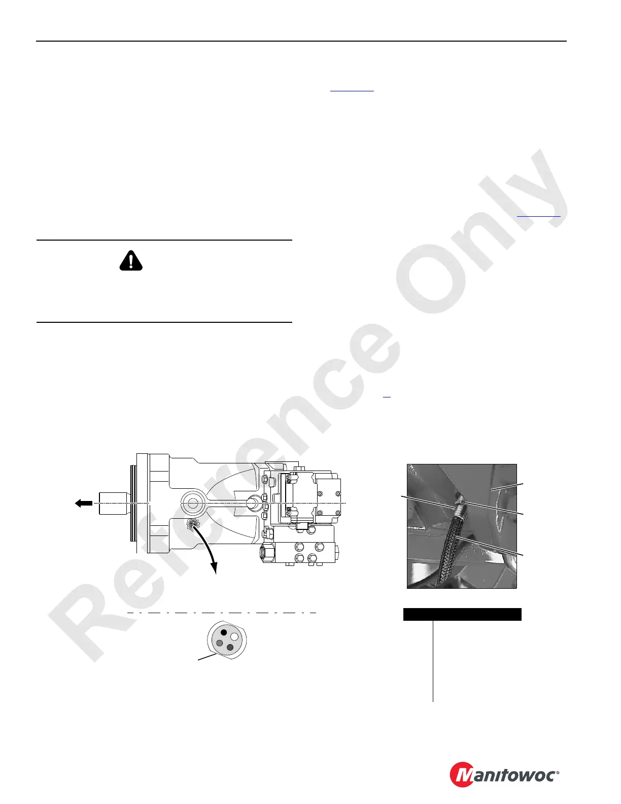
Version 1 – Sensor with Flats
See Figure 5-3 for the following procedure.
1. Bring corresponding function to a complete stop, land
suspended load if load drum is being serviced, and
PARK function.
2. Remove faulty sensor. Do not connect sensor cable to
crane wire harness until initial adjustment is made.
3. Loosen lock nut and carefully turn sensor in (clockwise)
by hand until it gently contacts speed ring inside motor.
4. Back sensor out (counterclockwise) 1/4 turn or more
until flat on sensor is positioned as shown in Figure 5-3
.
5. Connect sensor cable to crane wire harness.
6. Operate drum motor and check for a steady drum speed
(rpm) signal on drum screen in cab.
If necessary, turn sensor out slightly until drum speed
(rpm) is steady at low and high rpm.
7. Check for proper
drum direction (+/-) on corresponding
drum screen.
• + (plus) = RA
ISE
• - (minus) = LOWER
If proper direction is not indica
ted, turn sensor out
180°.
8. Repeat step 6.
9. Hold sensor in position and securely tighten lock nut.
WARNING
Hot Oil!
Hot oil will drain from motor port when sensor is removed.
Wait for hydraulic oil to cool before removing sensor.
Orientation is looking down
at drum motor sensor at
bottom side port.
P1763a
Typical Speed Sensor Location
TOP OF
MOTOR
FIGURE 5-3
Item Description
1 Flat on Sensor
2Motor
3 Lock Nut
4Cable
5 Gearbox
6Flat
7 Centerline of Motor
5
3
4
7
2
1
6
18CSM5-103

 Loading...


