ELECTRIC SYSTEM 18000 SERIVCE/MAINTENANCE MANUAL
3-28
Published 12-05-17, Control # 035-23
NODE 0 - Power, Engine Controls, and Diagnostics
Reference Electrical Schematic A06374 - Sheet 15
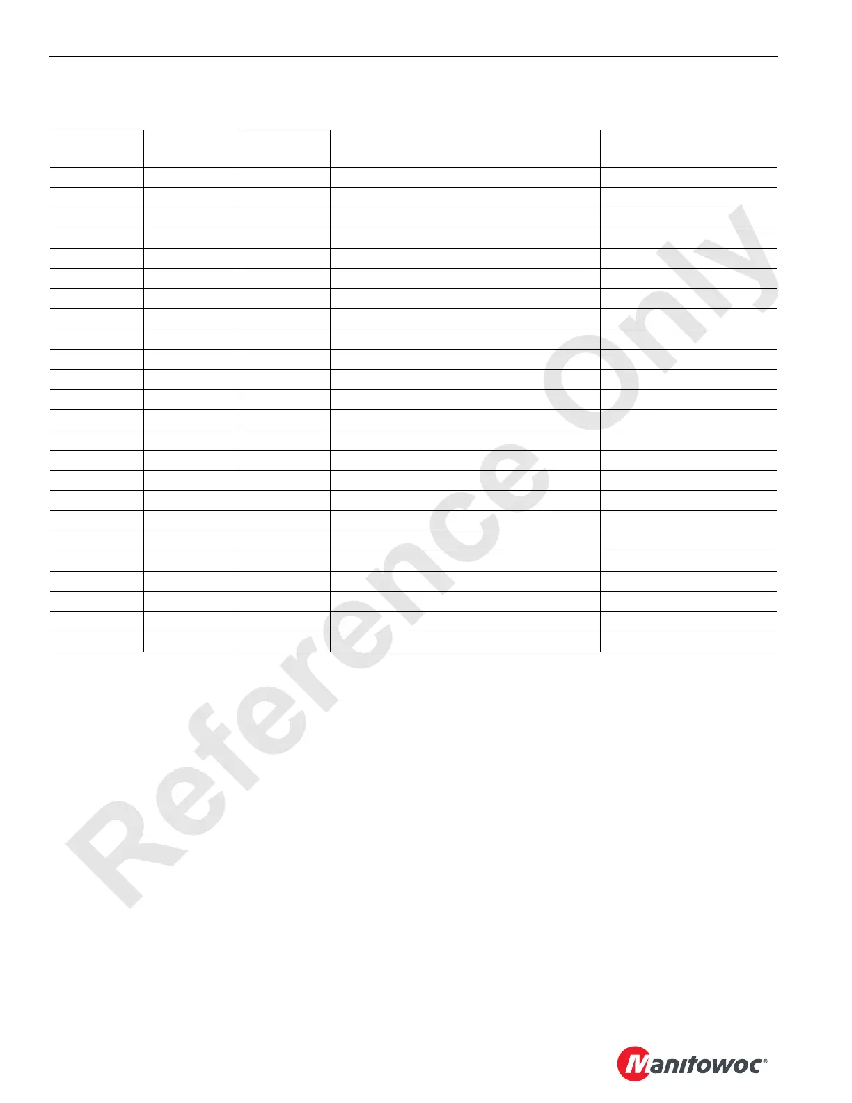
Receptacle/
CAN/ID
Wire No.
Function
Type
Description Test Voltage
J1 Connector – 40 Pin
P11 3 24 Volts Ignition Signal 24 Volts Nominal
P12 0102 Ground Can System Bus Ground
P13 0103 DO-1 Ether Relay Coil - Positive 24 Volts
P14 0104 24 Volts ECM Power Relay Coil - Positive 24 Volts
P17 0107 24 Volts Air Conditioning Clutch Relay Coil - Positive 24 Volts Nominal
P110 0110 24 Volts MS1/MS2 Start Relay Coil - Positive 24 Volts Nominal
P111 0 Ground Battery Ground
P112 0112 Ground Can System Bus Ground
P114 0114 Ground ECM Power Relay Coil - Negative Ground
P117 0117 Ground Air Conditioning Clutch Relay Coil - Negative Ground
P119 0119 Ground Ether Relay Coil - Negative Ground
P120 0120 Ground MS1/MS2 Start Relay Coil - Negative Ground
P121 OC Ground Can System Bus Output Wire Ground
P122 0122 Ground Can Power Relay Coil - Negative Ground
P129 RS232GND Ground Common Ground
P130 RS232PE Signal Program Enable N/A
P131 8C 24 Volts Can Power Relay Output 24 Volts Nominal
P132 0132 24 Volts Can Power Relay Coil - Positive 24 Volts Nominal
P133 3 24 Volts Ignition Signal 24 Volts Nominal
P136 J1939H Signal Communication – High N/A
P137 J1939L Signal Communication – Low N/A
P139 RS232TX Signal Program Transmit N/A
P140 RS232RX Signal Program Receive N/A

 Loading...


