Manitowoc Published 12-05-17, Control # 035-23 3-3
18000 SERIVCE/MAINTENANCE MANUAL ELECTRIC SYSTEM
TEST VOLTAGES
CAN Bus Nodes
The Model 18000 operating system is an EPIC
®
(Electrical
Processed Independent Control) with Can-Bus technology.
The can bus system uses multiple nodes that contain
controllers. The controllers communicate with node 1
(master) controller by sending data packets over a two-wire
bus line. The data packets are tagged with addresses that
identify system components of each node.
A wireless hand-held radio remote is used for operating
setup items.
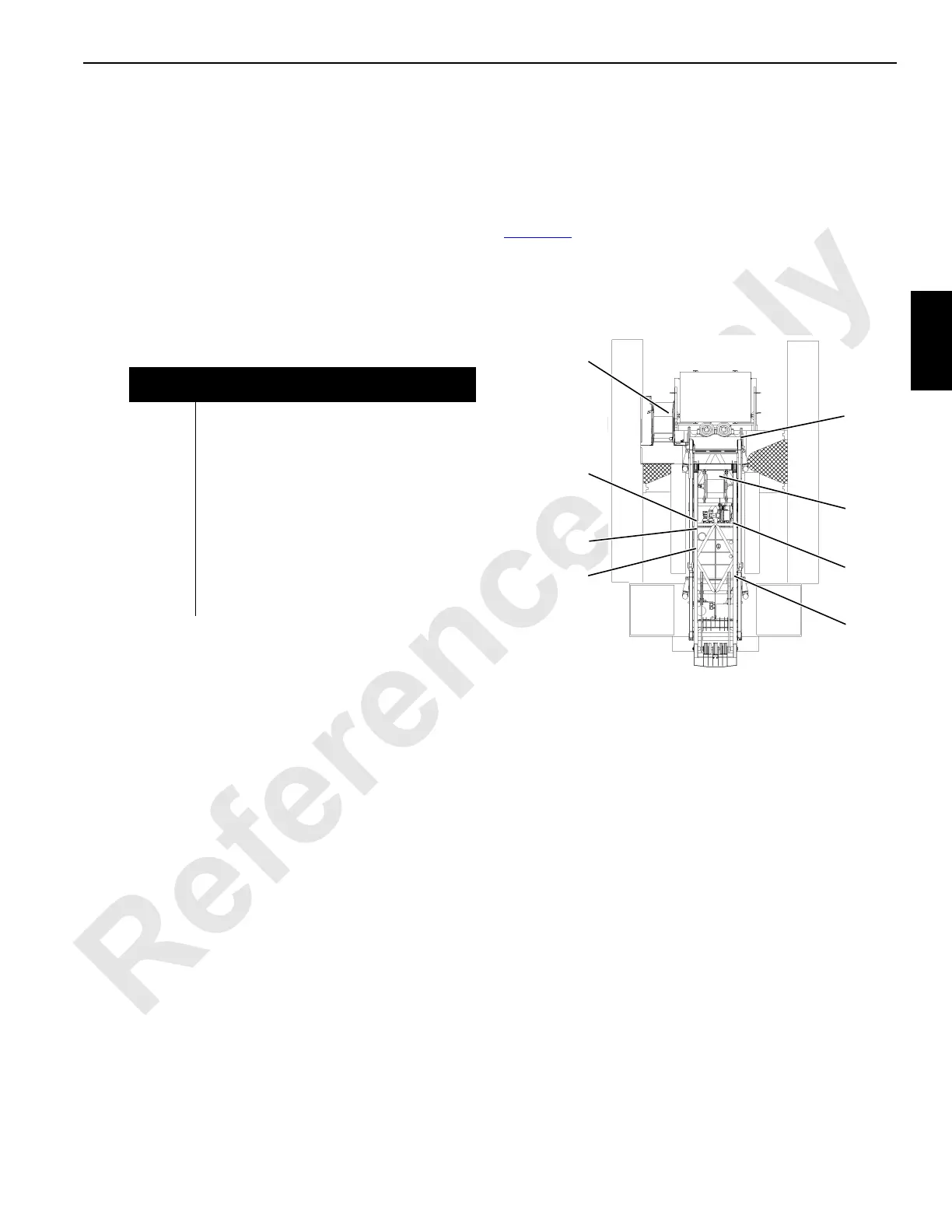
Test voltages are sorted by nodes (reference Electrical
Schematic A06374). The nodes are listed and identified in
Figure 3-1
.
Node
Number
Node
1 Master (Front Console)
2 Handles and Cab Controls
3 Drum 3 and Pressure Senders
4 Jacking, Connecting Pins, and Mast
5 Alarms, Limits, and Pump Controls
6 Drums 2, 4, 5, and Adapter Frame Pins
7 Swing, Travel and Auto Lube
8 Drum 1 and Drum 6
9MAX-ER
0 Power, Engine Controls, and Diagnostics
20 Boom Block Up, Block Sensor, & Limits
21 Luffing Jib Block Up, Block Sensor, & Limits
FIGURE 3-1
6
0
7
3
2
1
In Right Side
Cab Console
5
9
4
18CSM3-101
21 is on Jib Top
20 is on Boom Top
8 is on Boom Butt
 Loading...


