HYDRAULIC SYSTEM 18000 SERIVCE/MAINTENANCE MANUAL
2-32 Published 12-05-17, Control # 035-23
Charge Pressure Check
See Figure 2-23 and 2-27 for the following procedure.
The charge pressure line of the calibration screen indicates if
any charge pump is not within 275-400 psi (19-27 bar).
Charge pressure should be checked at the following
intervals:
• When a new controller node is installed
• When a pump is replaced
• When a pump control (EDC or PCP) is replaced
• Every 6 months
To check charge pressure, proceed as follows:
1. Start and run engine at low idle
2. Access calibration screen shown below as follows:
a. Turn LIMIT BYPASS switch clockwise and hold.
b. SCROLL UP at least one screen.
c. Continue to scroll up or down until calibration screen
appears.
d. The fourth line of the screen indicates charge
pressure:
- If 0 appears, all charge pumps are okay.
- If any number other than 0 appears, use Table
2-11 to determine which pumps have failed the
test.
Each pump is assigned a number in the binary
system. Outputs that are ON (failed) for any
pump, are added together. To identify the failed
pumps, find the binary number displayed on the
screen in the first column of Table 2-11
. All
shaded boxes to the right of the number
indicate pumps that have failed. Troubleshoot
the particular system to determine the cause of
the fault.
e. Proceed to next procedure, or exit calibration
screen by pressing bottom of CRANE MODE
switch. Cursor (*) will disappear from screen.
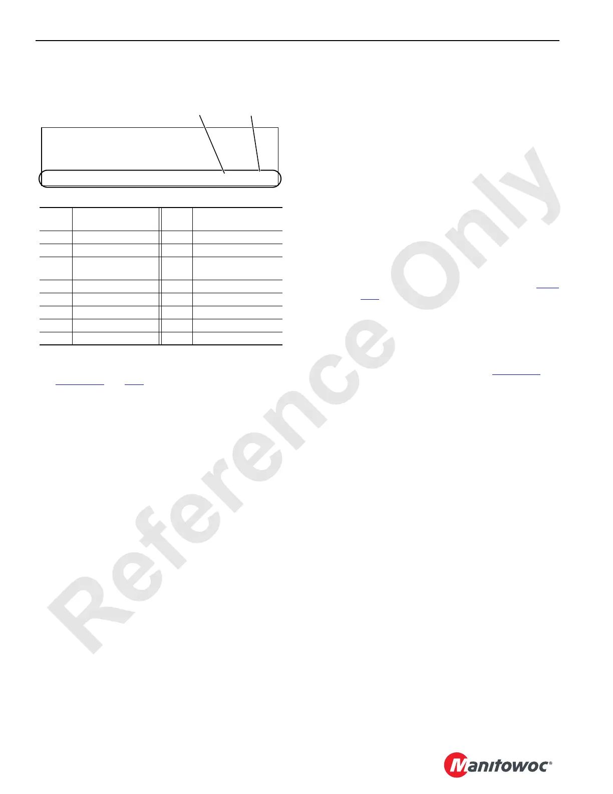
FIGURE 2-27
Binary
No.
Pressure Sender
(Bank 1)
Binary
No.
Pressure Sender
(Bank 2)
1 Drum 1/3 (Main Hoist) 1 Swing Left
2 Not Used 2 Swing Right
4 Drum 2/5 (Main Hoist) 4
High Pressure
Accessory Accumulator
8 Accessory System
16 Drum 4 (Boom Hoist)
32 Drum 6 (Luffing Hoist)
64 Left Track
128 Right Track
PRESSURE SENDER CAL
CONTROL CAL
PUMP PRESSURE TEST
CHARGE PRESSURE 32 0
Binary
Number 1
Binary
Number 2
 Loading...


