Grove Published 3-23-2020, Control # 654-04 4-81
GRT655/655L OPERATOR MANUAL OPERATING PROCEDURES
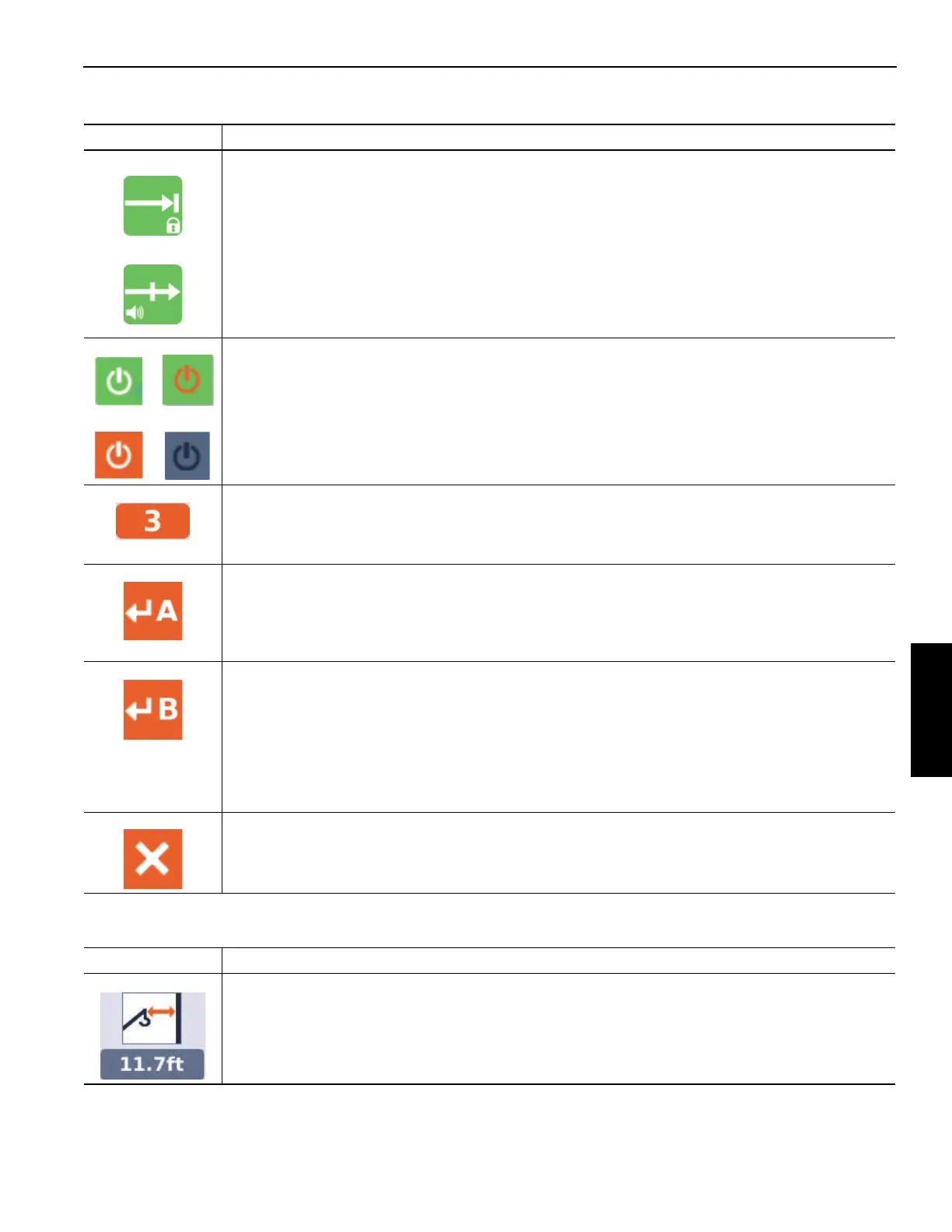
Table 4-10 Screen Symbols
In addition to the symbols that can be highlighted by the
arrow functions, the following are shown on the screen:
Symbol Description
Lock Out symbol and Alarm/Warning symbol - These symbols will not appear if the WRL is configured
for only the Lock Out Function or only the Alarm/Warning Function. Standard cranes are configured
for only the Alarm/Warning Function. Cranes configured for both functions, Lock Out and
Alarm/Warning, give the operator the ability to toggle between these two symbols, which indicate the
selection for the Lock Out Function (top symbol) or the Alarm/Warning Function (bottom symbol). The
selection for this configuration is toggled with an OK button (2, Figure 4-40).
Enable symbol - this symbol is used to enable or disable the limitation. The selection for this option is
changed with an OK button. The symbols shown on the top (green background) indicate that the
limitation is enabled. The symbols shown on the bottom (not green background) indicate that the
limitation is disabled.
Virtual Wall Number - this is used to indicate the virtual wall that is being defined or altered (there can
be up to 5 virtual walls). If the limitation is enabled, and this symbol is highlighted (orange
background), the value can be changed with the Up Arrow and Down Arrow function on the display or
jog dial (using an OK button to begin and complete the value entry).
Accept Crane Position Point A symbol - If the limitation is enabled, this symbol allows the acceptance
of the current crane position (in terms of hook radius and swing angle) to be the first point (Point A) of
a line that defines the position and orientation of the virtual wall. If this symbol is highlighted (as shown
here with orange background), and the crane position is accepted with an OK button, then the Point A
is considered defined.
Accept Crane Position Point B symbol - If the limitation is enabled, this symbol allows the acceptance
of the current crane position (in terms of hook radius and swing angle) to be the second point (Point B)
of a line that defines the position and orientation of the virtual wall. If this symbol is highlighted (as
shown here with orange background), and the crane position is accepted with an OK button, then the
Point B is considered defined. Note that if the Point A and Point B are not in allowable positions, a fault
will be generated, and a fault symbol will appear on the display. For instance, the 2 points may not be
so close to each other that a virtual wall is not clearly defined; the 2 points should be at least 10 ft
apart).
Remove Virtual Wall symbol - If the limitation is enabled, and this symbol is highlighted (orange
background), this symbol removes the definition of the current wall.
Symbol Description
Wall Proximity Value - this value is the approximate distance from the boom nose to the nearest wall.
It becomes a negative value when the boom is protruding beyond the boundary of the wall.
 Loading...


