Grove Published 3-23-2020, Control # 654-04 4-95
GRT655/655L OPERATOR MANUAL OPERATING PROCEDURES
2
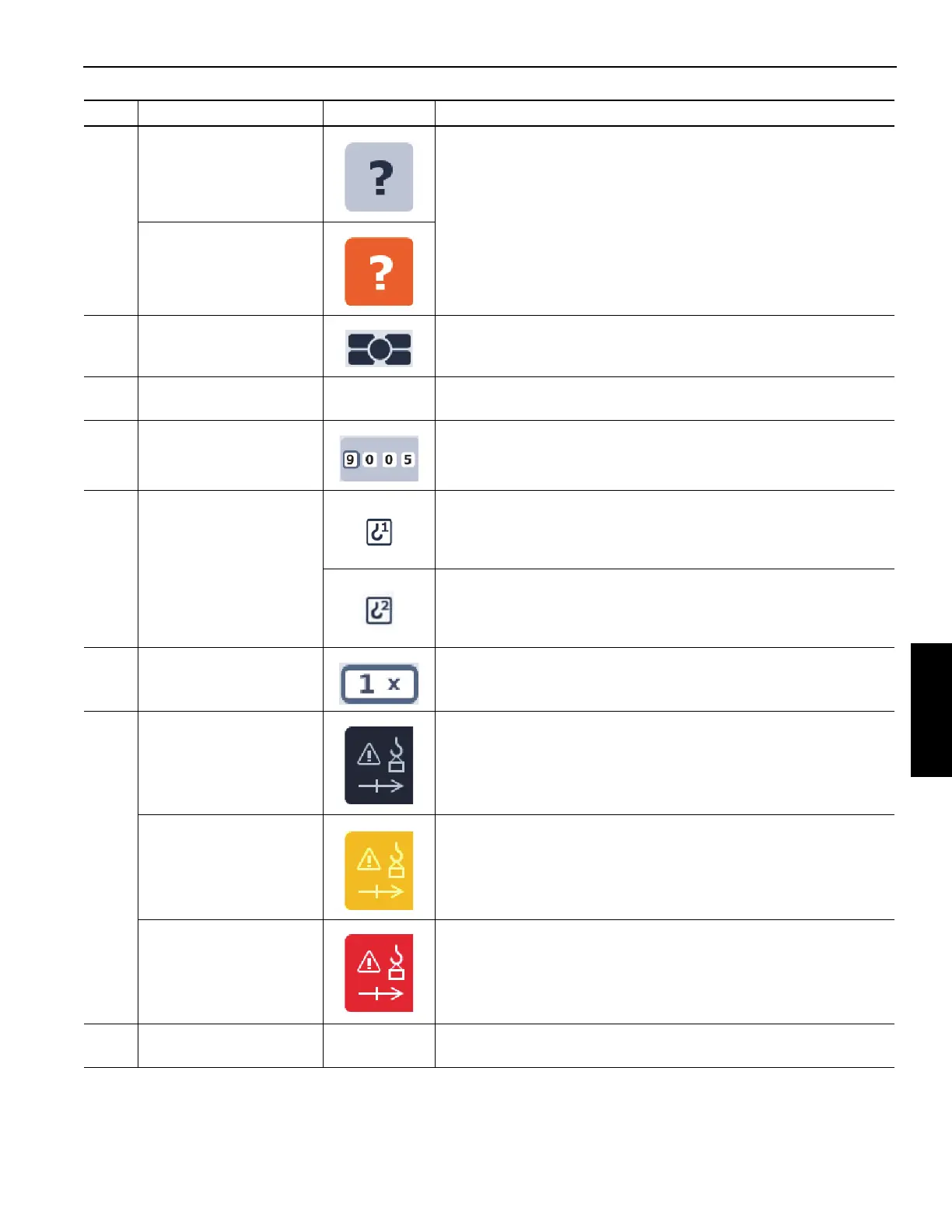
RCL Setup Wizard icon
- not selected
Icon used to select the RCL Setup Wizard.
RCL Setup Wizard icon
- selected
3
Jog Dial Status
Indicator
Indicates the RDM screen is being controlled by the Jog Dial. Refer
to Navigating the Operator Display Module and Rated Capacity
Limiter Display Module, page 4-34.
4 Crane Pictorial
—
Graphical representation of the programmed RCL crane
configuration.
5
Load Chart Code
Number
Load Chart Code Number for the programmed RCL crane
configuration.
6
Active Hoist
Programmed into RCL
Indicates the main hoist is programmed into the RCL as the active
hoist.
Indicates the auxiliary hoist is programmed into the RCL as the
active hoist.
7 Parts of Line Indicates the number of parts of line programmed into the RCL.
8
Limit Bypass Indicator Indicates that none of the crane function limiters are bypassed.
Limit Bypass Indicator
(Amber - flashing)
Indicates the Limit Bypass Switch behind the operator’s seat is in the
bypassed position when the ignition switch is set to the On position.
Make sure Limit Bypass Switch is in the non-bypassed position prior
to turning the ignition switch to the On position.
Limit Bypass Indicator
(Red)
Indicates a Limit Bypass Switch is in the bypassed position.
9
Wind Speed Indicator
(optional)
—
Indicates wind speed in kph or mph.
Item Description Graphic Explanation
 Loading...


