Grove Published 3-23-2020, Control # 654-04 5-11
GRT655/655L OPERATOR MANUAL SET-UP AND INSTALLATION
Of the methods shown, Grove prefers method A or F be used
on Grove cranes, i.e., clipping a short piece of wire rope to
the dead-end or using a commercially available specialty clip
(1) or wedge (2). It is recommended the dead-end tail length
be a minimum of 6 rope diameters, but not less than 15.2 cm
(6 in) for standard 6 to 8 strand ropes. For rotation resistant
rope, the dead-end tail length must be a minimum of 20 rope
diameters, but not less than 15.2 cm (6 in).
When using method A, place a wire rope clip around the
dead end by clamping a short extra piece of rope to the rope
dead end. DO NOT CLAMP LIVE END. U-bolt should bear
against the dead end. Clip saddle should bear against the
short extra piece. Torque U-bolts to values listed in Table 5-1.
NOTE: Use of swivels is not allowed with non-rotation
resistant wire ropes.
Other sources for information with which crane users should
be familiar and follow is provided by the American Society of
Mechanical Engineers, American National Standard, ASME
B30.5, latest revised. ASME (formerly ANSI) B30 applies to
cableways, cranes, derricks, hoists, hooks, jacks, and slings.
It states, in section 5-1.7.3, “(c) Swaged, compressed, or
wedge socket fittings shall be applied as recommended by
the rope, crane or fitting manufacturer.” Wire ropes are
addressed in ASME B30.5, section 5-1.7.2, ROPES, It
states, in pertinent part, “(a) The ropes shall be of a
construction recommended by the rope or crane
manufacturer, or person qualified for that service.” Additional
information is published by the Wire Rope Technical Board in
Wire Rope Users Manual, latest revision.
Table 5-1. Wire Rope Clip Torque Values
Clip Size Torque*
mm In N-m ft-lb
3.18 1/8 6 4.5
4.76 3/16 10 7.5
6.35 1/4 20 15
7.94 5/16 40 30
13.28 3/8 60 45
11.11 7/16 90 65
12.70 1/2 90 65
14.29 9/16 130 95
15.88 5/8 130 95
19.05 3/4 175 130
22.23 7/8 300 225
25.40 1 300 225
28.58 1-1/8 300 225
31.75 1-1/4 490 360
38.68 1-3/8 490 360
38.10 1-1/2 490 360
*Torque values are based on threads being clean, dry,
and free of lubrication.
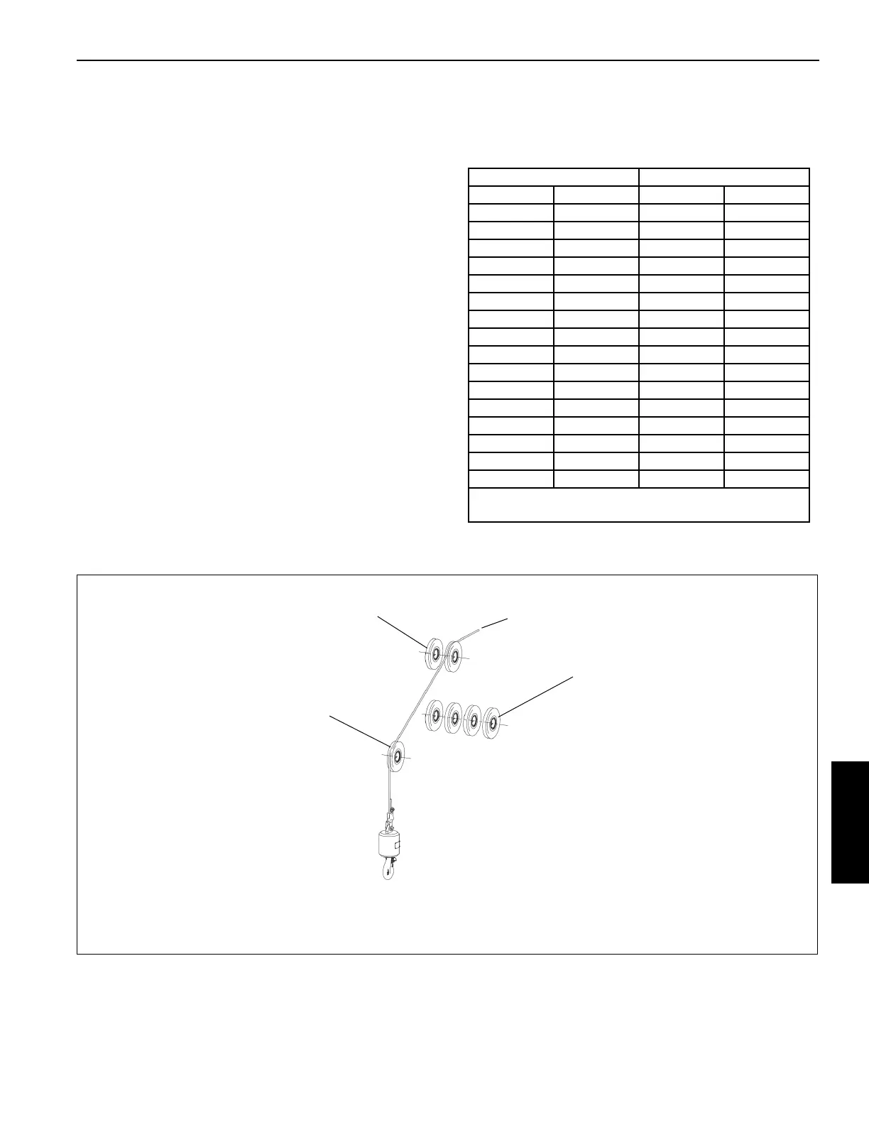
FIGURE 5-15
Single Part Line - Auxiliary Nose
To M ain H oi s t
Upper Boom Nose
Sheaves
Lower Boom
Nose Sheaves
8993-17
Auxiliary Boom
Nose Sheave
 Loading...


