3-2 Published 11-22-2016, Control # 345-12
ELECTRICAL SYSTEM RT9130E-2 SERVICE MANUAL
Batteries
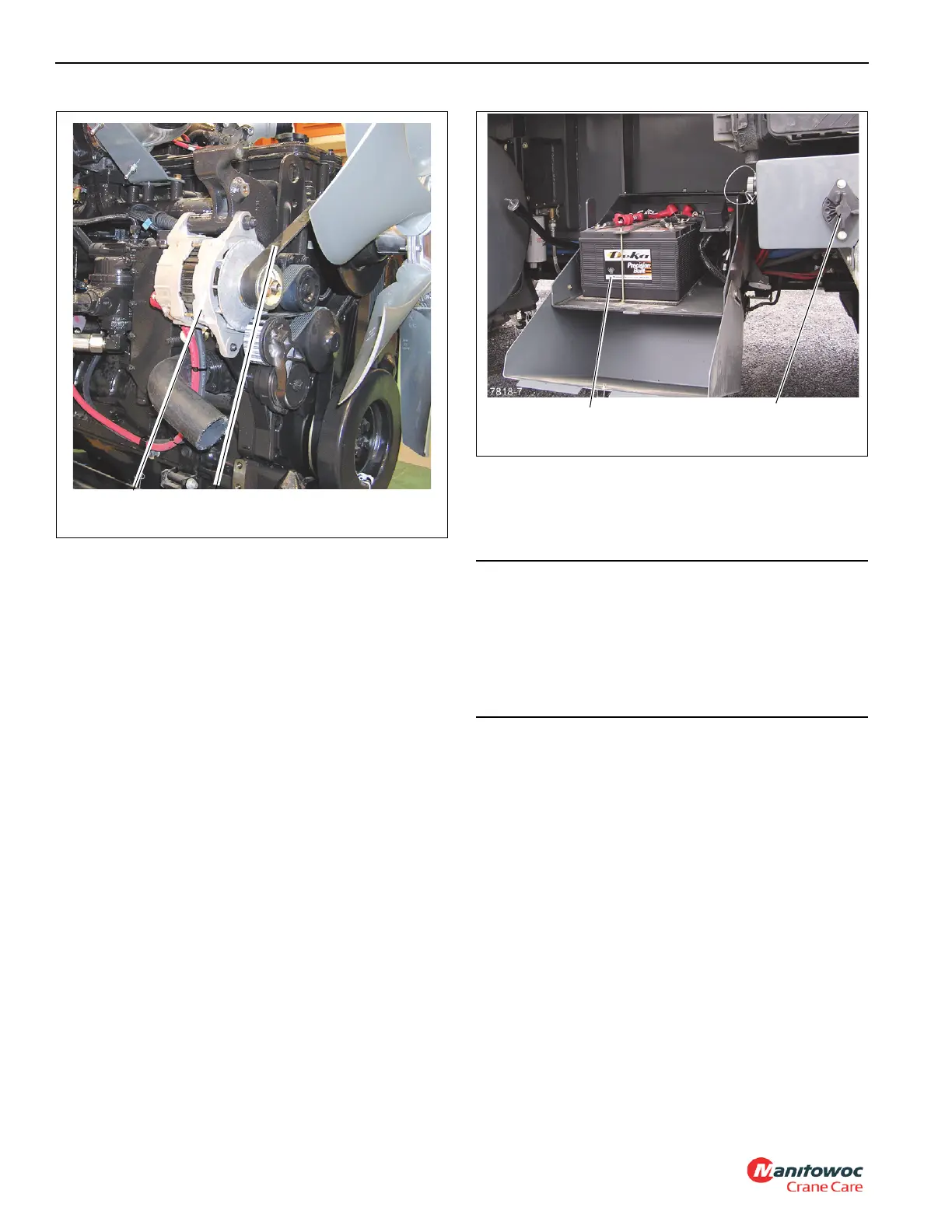
The batteries (Figure 3-2) are located in the battery box on
the left side of the crane behind the fuel tank. Each battery is
the maintenance free type and is completely sealed except
for a small vent hole in the side. The vent hole allows what
small amount of gases that are produced in the battery to
escape. On some batteries, a test indicator located on the
top of the battery is used to determine if the battery can be
tested in case of a starting problem.
A battery disconnect switch is located on the right side of the
battery box (Figure 3-2).To disconnect the batteries, turn the
battery disconnect switch to OFF. Turn the switch to ON to
connect the batteries.
Fuse Panel
NOTE: Refer to the electrical schematic in the back of this
manual for a diagram of the electrical system.
Most electrical circuits are protected by the components of
the relay panel assembly and the fuse panel.
The fuse panel (Figure 3-3 and Figure 3-4) is located behind
the seat and contains up to 20 fuses. To gain access to the
fuses, remove the snap-on cover. A decal in the cover
identities each fuse and its function.
Fuses 1, 2, 3, 4, 5, 6, 7 and 8 are energized when the battery
is connected. When the battery is connected and the ignition
switch is in the ignition (run) or accessory power position,
fuses 9 to 12 are energized through ACC relay #1 (K1) and
13 to 20 are energized through ACC relay #2 (K2).
FIGURE 3-1
7333-5
Alternator Alternator Belt
CAUTION
Possible Equipment Damage!
To avoid possible engine fault codes and undesirable
operation, ensure the keyswitch has been off two minutes
before disconnecting batteries.
Disconnect batteries, if machine will be inactive for over
24 hours.
FIGURE 3-2
Batteries
Battery Disconnect Switch
 Loading...


