Grove Published 11-22-2016, Control # 345-12 4-7
RT9130E-2 SERVICE MANUAL BOOM
extension of the sections, an indictor light on the console
remains illuminated as long as the unsynchronized condition
persists, and the inner mid or center mid section telescope
cylinder selection is indicated by respective lights on the
control panel, thereby allowing the operator to telescope the
section[s] appropriately). As long as the system continues to
detect the unsynchronized condition, and/or the manual
mode is selected, the rated capacity limiter/lockout system
also limits the allowable load moment to 22,046 lb (10,000
kg) or 50% of the rated capacity at the particular prevailing
boom length, the intent being that, while the sections are
unsynchronized, any hook load will be deposited, only the
hookblock remaining suspended while the necessary
adjustment of the boom sections occurs: only when
synchronization has been achieved will the system reset and
normalize the load monitoring system when switched back to
Automatic mode.
The standard used by the system to define an
unsynchronized condition is an error or +/-3% of the full
extension value of one section. Since the inner mid, center
mid, and the outer mid/fly combination all extend individually,
compliance with the criterion can only be assessed at
section extensions corresponding to the points of
changeover of movement from section to section. Therefore,
the system reviews the extension of each section prior to
permitting the changeover, and unless all section extension
values are within 3% of their programmed changeover
length, the system defaults to the out-of-synchronization
condition described above. The same default occurs if, in the
course of operation, any boom section moves out of
synchronization to a length corresponding to one of its own
changeover lengths (since it then invokes the +/-3% criterion
against the other sections), or moves away from such a
changeover length by more than the 3% margin.
BOOM MAINTENANCE
Removal
NOTE: The boom weighs approximately 36,610 lb (16,606
kg). Removal of the swingaway boom extension
will simplify boom removal, therefore, the above
weight is for the boom without the swingaway
boom extension attached.
1. Extend and set the outriggers to level the crane and
ensure the boom is fully retracted and in a horizontal
position over the front of the crane.
2. If equipped, remove the swingaway boom extension and
aux nose according to the removal procedures in this
section.
3. Remove the hookblock or headache ball and wind all the
wire rope onto the hoist drum.
4. Position the boom to make sure that the lift cylinder is
resting securely in the lift cylinder support.
5. Attach a lifting device to the boom to provide for equal
weight distribution.
6. Tag and disconnect any electrical wiring from the boom.
7. Tag and disconnect the hydraulic lines to the lower
telescope cylinder and plug.
8. Remove the capscrews, washers and nut fasteners
securing the base cover to the top of the boom base
section near the pivot shaft. Remove the cover.
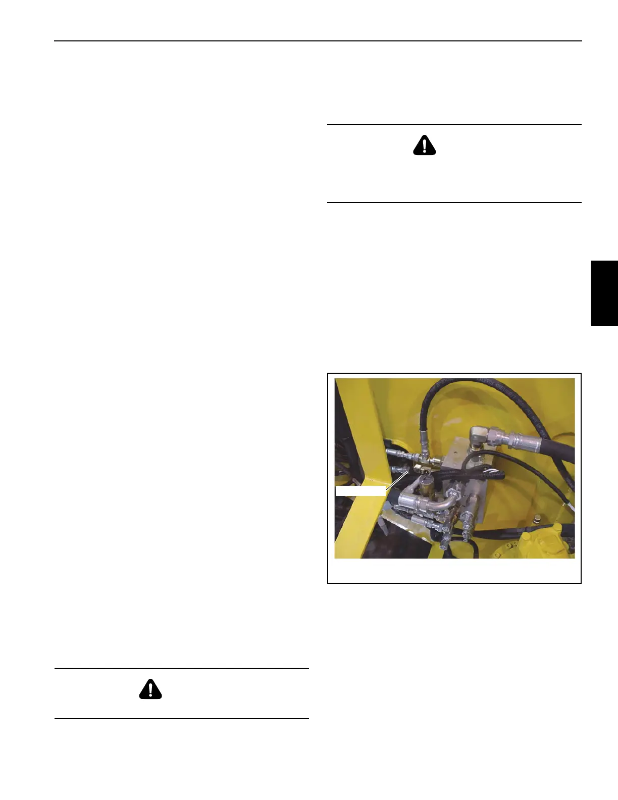
9. With the engine off, disconnect the hose reel supply line
from the side of the valve bank (Figure 4-3). Plug or cap
all openings.
10. Using the S-hook, secure the spring loaded side of the
hose reel in the turntable to prevent the reel from rotating
before proceeding to the next step (Figure 4-4). Reach
through the hole in the top of the base section and tag
and disconnect the hose reel lines from the hydraulic
manifold that is mounted on the rear of the center mid.
Cap all lines and openings. Feed the hoses through the
rollers at the rear of the base. If crane is being readied
for transport, secure the hoses to the hoist.
CAUTION
Wear gloves when handling wire rope.
DANGER
Crushing Hazard!
Ensure blocking and lifting devices are capable of
supporting the boom assembly.
Supply Hose
FIGURE 4-3
7700-2
 Loading...


