2-30 Published 11-22-2016, Control # 345-12
HYDRAULIC SYSTEM RT9130E-2 SERVICE MANUAL
Procedure M - For Checking Charge Air
Cooler Circuit Relief Valve Pressure (Tier 3
Only)
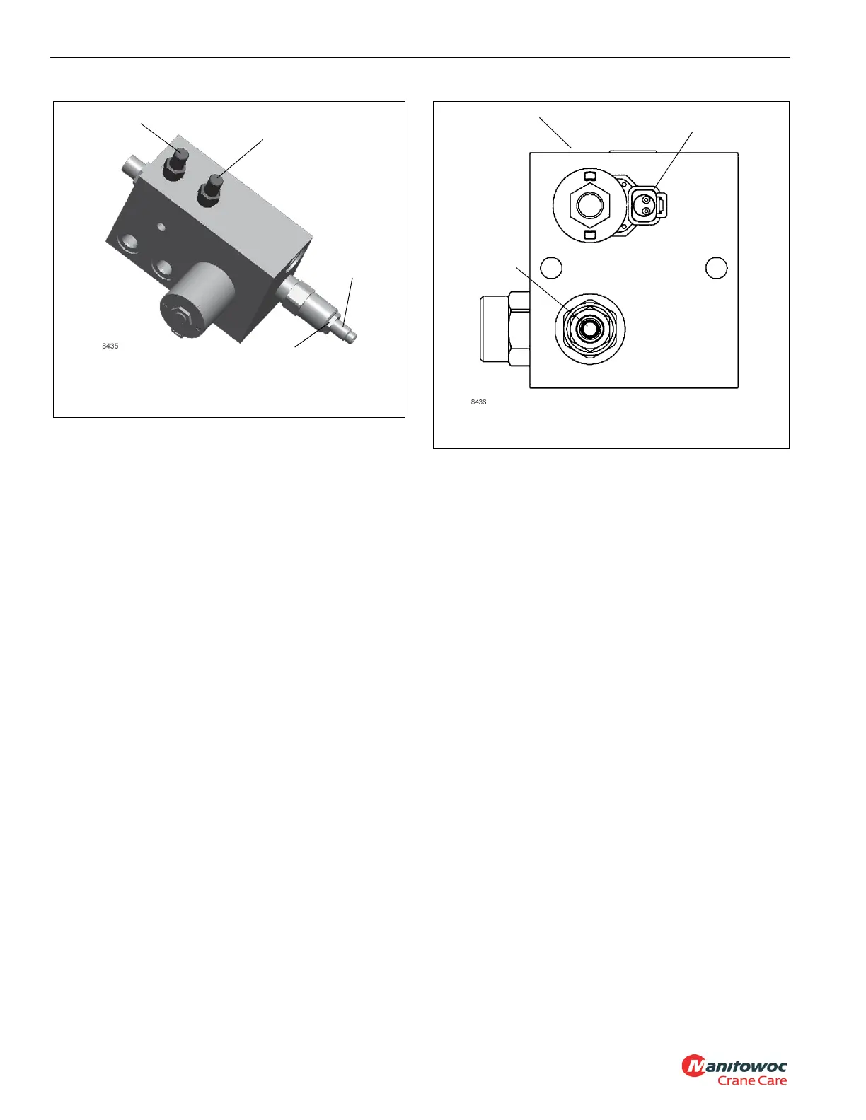
1. Install a pressure check diagnostic quick disconnect
(Parker PD240) with gauge onto test nipple @ the
Charge Air Cooler Motor Control Valve (Figure 2-16).
2. With engine at full RPM, unplug harness connection on
control solenoid to turn cooler on. Adjust relief valve to
obtain a reading of 1700 ± 50 PSI (11.7 ± 0.4 MPa). Turn
in to raise, out to lower.
3. Stop engine. Remove the diagnostic coupler. Re-
connect wires to solenoid.
Checking Charge Air Cooler (CAC) Motor
Control Valve – Tier 3 Only
1. Install pressure check diagnostic quick disconnect
(Parker PD240) with gauge onto test nipple at Charge
Air Cooler Motor Control Valve.
2. With engine at full RPM, unplug harness connection on
control solenoid to turn cooler on. Adjust relief valve to
obtain a reading of 1700 ± 50 psi (11.7 ± 0.4 MPa). Turn
in to raise, out to lower.
3. Remove pressure gauge and plug harness connection
back into control solenoid.
FIGURE 2-15
Make-up Oil Manifold
GPB
Adjustment
Stem
Loosen Locknut to
make adjustment
GPA
FIGURE 2-16
Charge Air Cooler Motor Control Valve
Gauge Port
Solenoid
Connection
Relief Valve

 Loading...


