2-26 Published 11-22-2016, Control # 345-12
HYDRAULIC SYSTEM RT9130E-2 SERVICE MANUAL
Procedure F - For Checking Accumulator
Pre-Charge Pressure
1. With the engine off, discharge all of the pressurized oil
stored in the accumulators by depressing the service
brake pedal on the cab floor several times. Remove the
gas valve guard and cap on the accumulator
(Figure 2-11).
2. Before attaching the gas charging assembly
(Figure 2-11) onto the accumulator gas valve, back the
gas chuck “T” handle all the way out (counterclockwise).
3. Close the charging assembly bleed valve. Without
twisting hose, attach the swivel nut onto the gas valve
and tighten (10-15 lb-in).
4. Turn the gas chuck T-handle all the way down
(clockwise) to depress the core in the gas valve.
5. Check the pre-charge pressure. It should be 1400 psi
+50/-0 (9.7 MPa +0.4/-0).
6. If the pressure is 1400 psi +50/-0 (9.7 MPa +0.4/-0),
remove the charging valve assembly by turning the T-
handle all the way out on the gas chuck and then
opening the bleed valve (Figure 2-11).
7. Hold gas valve to keep it from turning. Loosen swivel nut
and remove charging assembly. Reinstall gas valve cap
and guard.
Procedure G - For Pre-Charging
Accumulator
1. With the engine off, discharge all oil stored in the
accumulators by pushing the service brake pedal
several times. Remove the gas valve guard and gas
valve cap on the accumulator (Figure 2-11).
2. Check that the nitrogen supply bottle valve is shut off,
then attach charging assembly hose to nitrogen bottle.
3. Before attaching charging assembly (Figure 2-11) to the
accumulator gas valve, back the gas chuck T-handle all
the way out (counterclockwise).
4. Close the charging assembly bleed valve. Without
looping or twisting hose, attach the swivel nut onto the
gas valve and tighten.
5. Turn the gas chuck T-handle all the way down
(clockwise) to depress the core in the gas valve.
6. Crack open the nitrogen bottle valve and slowly fill the
accumulator. Shut off the valve when the pre-charge
pressure is 1400 psi +50/-0 (9.7 MPa +0.4/-0).
7. If the pre-charge pressure is higher than 1400 psi +50/-0
(9.7 MPa +0.4/-0), then close the nitrogen bottle valve
and slowly open the bleed valve on the charging
assembly (Figure 2-11) until the pre-charge pressure is
correct.
8. Remove charging assembly by turning T-handle all the
way out (counterclockwise) on gas chuck and then open
bleed valve.
9. Hold gas valve to keep it from turning, loosen swivel nut,
and remove charging assembly. Replace gas valve cap
and guard.
Procedure H - For Checking Front Steer
Relief Valve Pressure
1. Remove cap and install pressure gauge on steer valve
load sense test port (Figure 2-12).
2. With the engine running at 1000 RPM, turn the steering
wheel to LOCK position and adjust pressure at the steer
priority flow divider section relief to 2500 psi
±50
(17.2 MPa
±0.4).
3. Remove pressure gauge from the Load Sense Test Port
and reinstall cap.
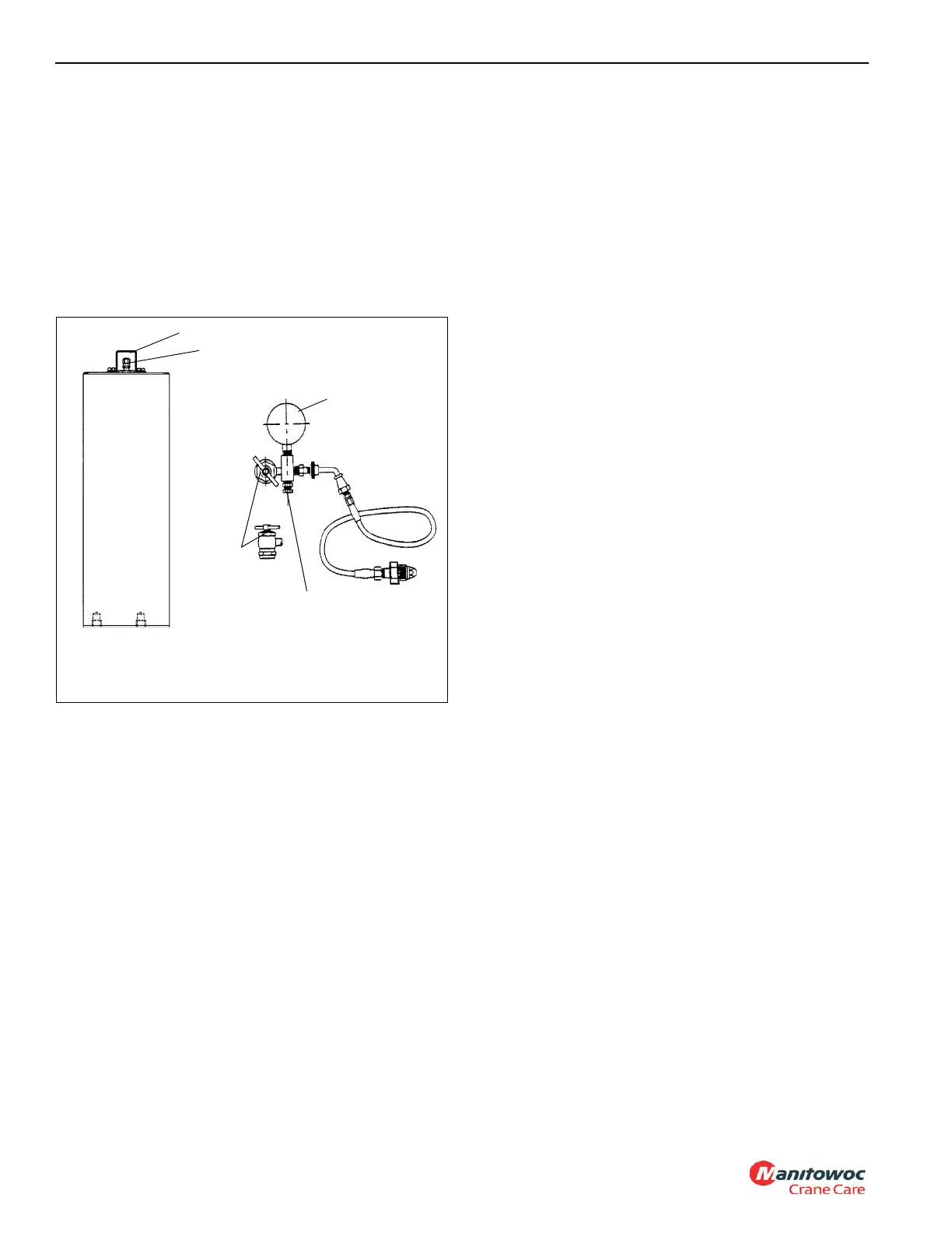
FIGURE 2-11
Gas Valve Guard
Gas Valve
Gauge
Bleed Valve
Gas
Chuck
6659-6
Accumulator
Charging Assembly

 Loading...


