Grove Published 11-22-2016, Control # 345-12 5-21
RT9130E-2 SERVICE MANUAL HOIST AND COUNTERWEIGHT
COUNTERWEIGHT REMOVAL AND
INSTALLATION
Counterweight Stand Installation
NOTE: The counterweight stands must be installed on the
front of the carrier before removing either the
standard or heavy counterweight assembly.
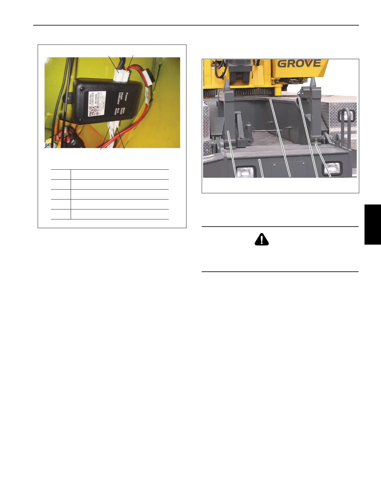
1. Using an adequate lifting device, install the
counterweight stands (1) (Figure 5-12) to the front of the
carrier frame (3) (Figure 5-12) and secure with the hitch
pins (4) (Figure 5-12).
2. Rotate foot plates (5) (Figure 5-12) on the counterweight
stands (1) (Figure 5-12) until they come to rest on top of
the front outrigger box (2) (Figure 5-12).
3. Adjust the foot plate (5) (Figure 5-12) and adjusting
screw (6) (Figure 5-12) into or out of the counterweight
support until the counterweight pads on top of the
counterweight support are level. Do not exceed 2.25 in
(5.72 cm).
4. Tighten jam nut (7) (Figure 5-12) against counterweight
support.
FIGURE 5-11
8425-1
Item Description
1 To LED Indicator
2 Power and Ground
3 Main Hoist Pressure Switches
4 Auxiliary Hoist Pressure Switches
1
2
4
3
DANGER
Adjustment of the counterweight stand (1) (Figure 5-12)
supports is prohibited when the counterweight (1)
(Figure 5-13) is resting on them.
7229
1
2
3
4
5, 6, 7
FIGURE 5-12

 Loading...


